Corrugated steel web box girder with steel-concrete combined board lower wing edges

A corrugated steel web and concrete technology, applied in bridges, bridge materials, bridge construction, etc., can solve the problems of reducing structural bearing capacity, stiffness and durability, difficulty in on-site operation and construction, and difficulty in popularization and application, and achieve reduction Formwork engineering and concrete wet work workload and formwork support process, shorten the construction period, and reduce the effect of on-site workload

Inactive Publication Date: 2008-10-08
TSINGHUA UNIV
View PDF0 Cites 14 Cited by
  • Summary
  • Abstract
  • Description
  • Claims
  • Application Information

AI Technical Summary

Problems solved by technology

When pouring the lower flange concrete slab, it is necessary to set up scaffolding and supporting formwork on site, and there are problems such as on-site operation and construction difficulty
On the other hand, the concrete slab of the lower flange is prone to cracking under the action of positive bending moment, and the cracks will reduce the bearing capacity, stiffness and durability of the structure
These problems have caused certain difficulties to the popularization and application of this type of structure.

Method used


Image

  • Corrugated steel web box girder with steel-concrete combined board lower wing edges
  • Corrugated steel web box girder with steel-concrete combined board lower wing edges
  • Corrugated steel web box girder with steel-concrete combined board lower wing edges

Examples


Embodiment Construction

[0015] Below in conjunction with accompanying drawing, structure of the present invention, construction process are described further.

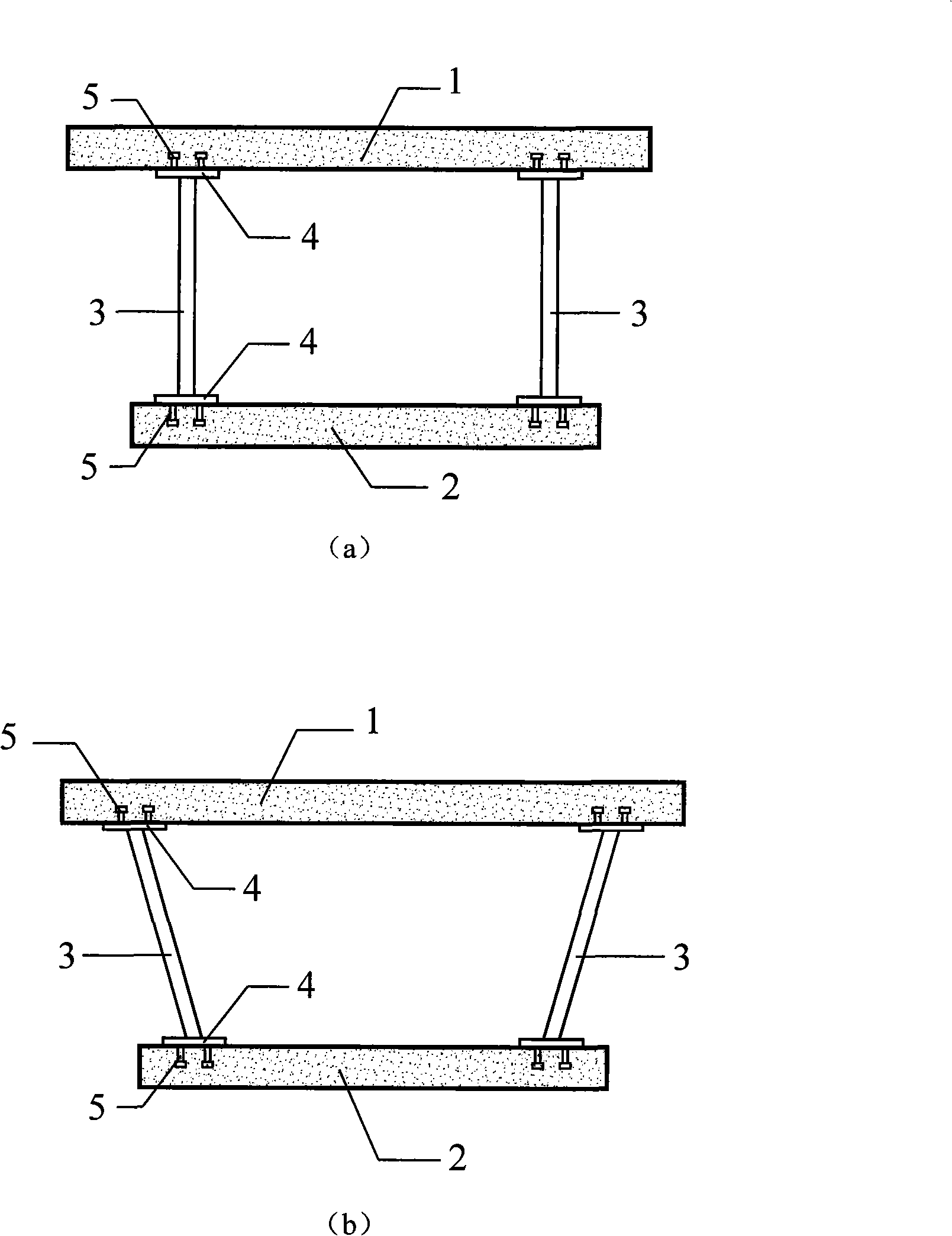
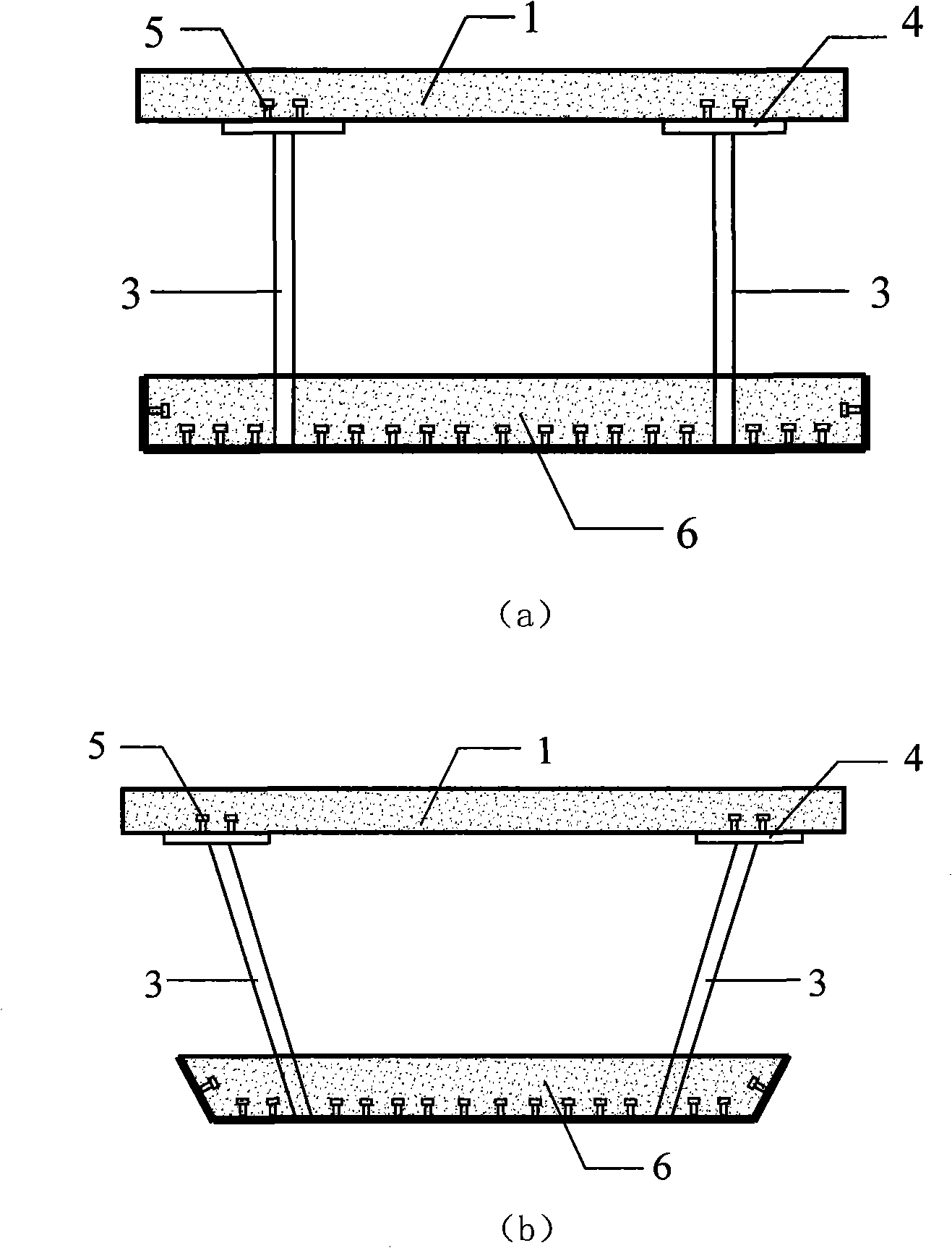
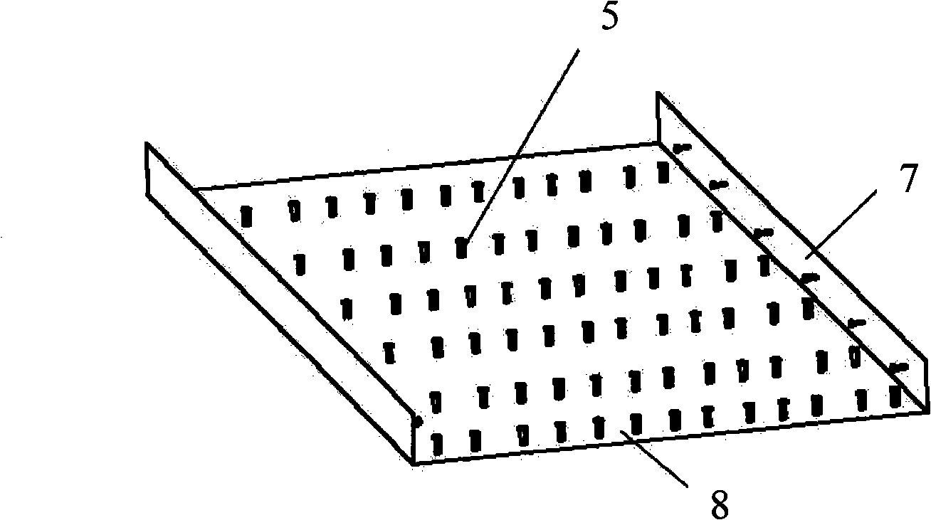
[0016] The invention provides a corrugated steel web box girder with a lower flange of a steel-concrete composite plate, which can reduce on-site workload and construction difficulty, and improve structural bearing capacity, rigidity and crack resistance. Such as Figure 2 to Figure 5 As shown, the box girder is composed of the upper flange concrete slab 1, the corrugated steel web 3 and the steel-concrete composite slab 6 of the lower flange. The steel-concrete composite plate 6 is made up of a channel-shaped steel plate welded with pegs 5 and concrete 10 poured inside the channel-shaped steel plate, and a reinforcement mesh sheet 9 is arranged in the middle of the concrete 10; the groove Shaped steel plate is made up of side plate 7 and base plate 8. The side panels can be placed vertically or obliquely, and the studs on the side panels a...


PUM


Abstract

The invention relates to a corrugated steel web box beam with steel-concrete composite plate bottom flange, in particular to a corrugated steel web box beam that is applied in railway and bridges. The corrugated steel web box beam is composed of a top flange concrete slab, a corrugated steel web and a steel-concrete composite plate bottom flange, wherein steel-concrete composite plate is composed of a slotted steel plate formed by side plates and bottom plates, and a concrete, the steel plate is welded with bolts and reinforced meshes are arranged at middle position of the concrete. The structure can overcome the problem that the traditional corrugated steel web box beam has complicated construction for steel structure positioning on the spot, and also can exert tensile strength of the steel plate so as to improve crack resistance of structure effectively and avoid crack from being exposed, so that structural endurance is improved obviously, therefore the work load and difficulty of the construction of concrete in-field casting of box beam bottom flange is reduced greatly. The corrugated steel web box beam with steel-concrete composite plate bottom flange has simple structure, rapid and convenient construction and is easy to meet the requirement of planar shape of bridge, and also has good technical economic benefit.

Description

technical field [0001] The invention relates to a corrugated steel web box girder with a lower flange of a steel-concrete composite plate, which can be applied to railway bridges and highway bridges; it belongs to the technical field of bridge structures. Background technique [0002] Traditional corrugated steel web concrete composite box girder, such as figure 1 As shown in (a) and 1(b), it consists of the upper flange concrete slab 1, the lower flange concrete slab 2 and two corrugated steel webs placed vertically or obliquely. The corrugated steel webs of each leg and the upper and lower After the steel plate of the flange is welded at the factory and transported to the construction site, it needs to be accurately positioned, which makes the construction difficult. When pouring the lower flange concrete slab, it is necessary to erect scaffolding and supporting formwork on site, and there are problems such as on-site operation and construction difficulty. On the other h...

Claims


Application Information

Patent Timeline
Patent Type & Authority Applications(China)
IPC IPC(8): E01D2/04E04C3/294E01D101/26E01D101/30
Inventor 聂建国吴丽丽
Owner TSINGHUA UNIV
Why Eureka
Try Eureka