
Relay

A technology of relays and electromagnets, applied in the field of high-frequency relays, to achieve the effects of small deviations in operating characteristics, fewer assembly processes, and high assembly accuracy

Inactive Publication Date: 2011-01-26
ORMON CORP
View PDF5 Cites 1 Cited by
  • Summary
  • Abstract
  • Description
  • Claims
  • Application Information

AI Technical Summary

Problems solved by technology

[0005] However, in the coaxial relay in which the permanent magnet 32 ​​is assembled on the yoke 29, the yoke 29 needs to be manufactured by stamping and bending the sheet material. As a result, the number of processing steps for parts is large
Particularly in the coaxial relay, when the permanent magnet 32 ​​is assembled on the yoke 29, the permanent magnet 32 ​​is positioned on the hanging pieces 29b, 29b of the yoke 29 and fixed with an adhesive. , there are the following problems, it is difficult to obtain high assembly accuracy, and the operating characteristics are prone to deviation, and the number of parts and the number of assembly processes are large

Method used


Image

  • Relay
  • Relay
  • Relay

Examples


Embodiment Construction

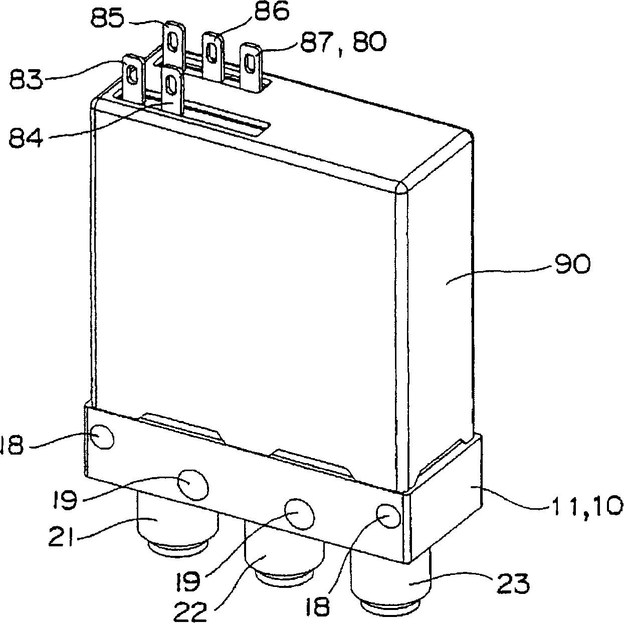
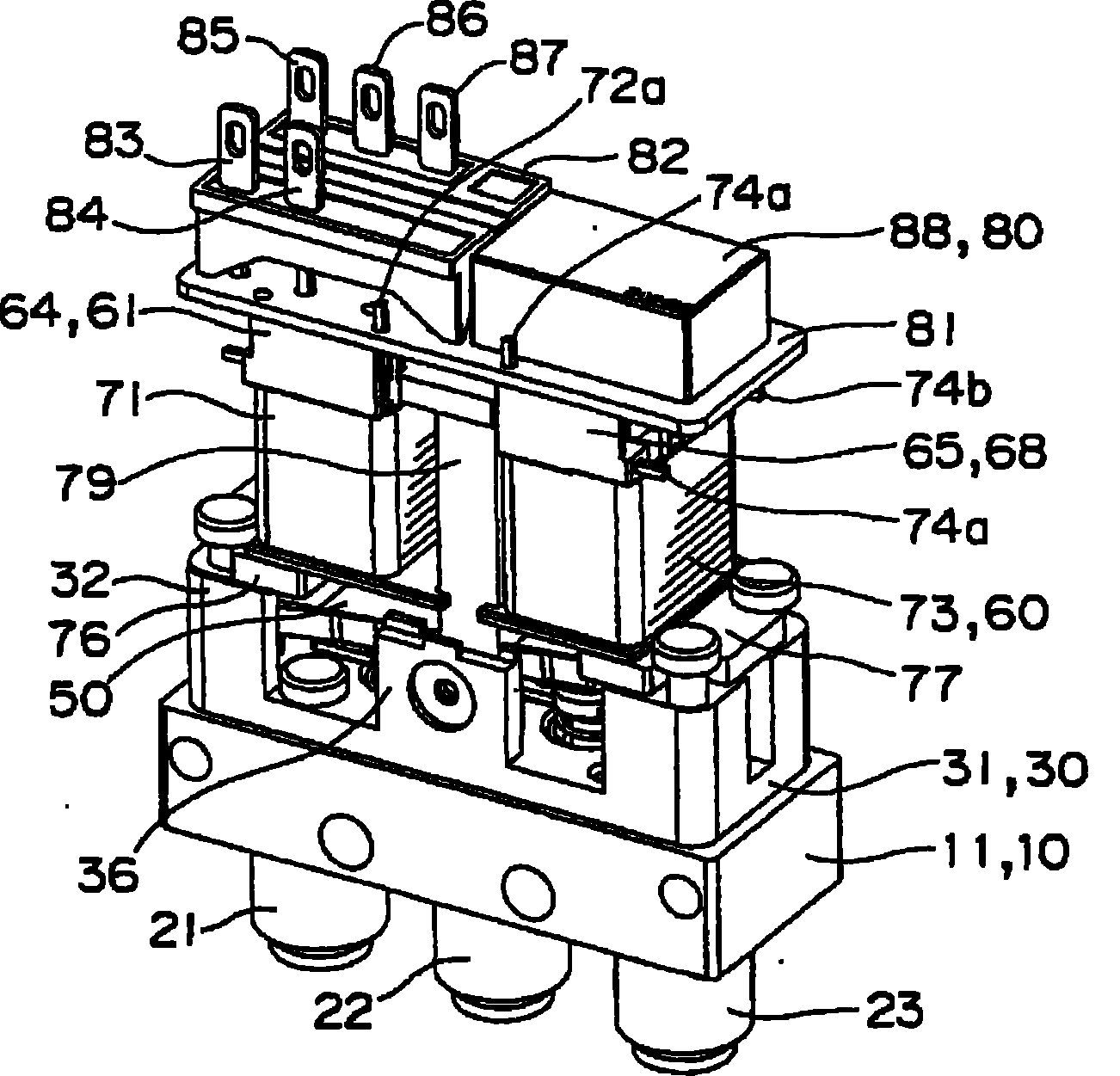
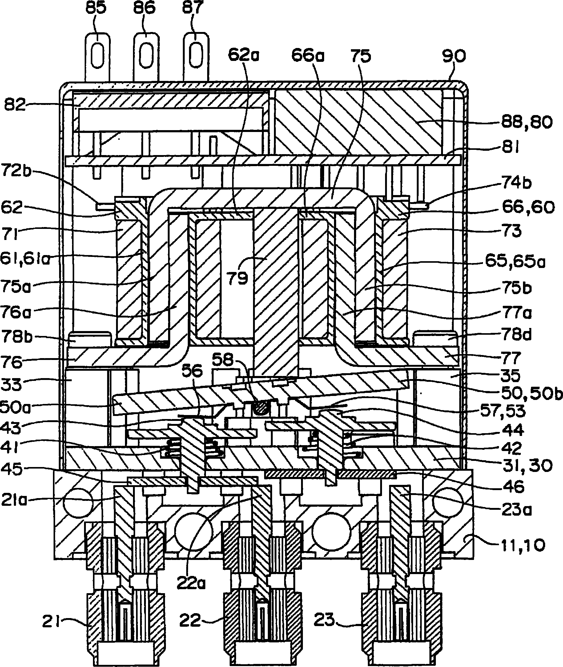
[0092] according to Figure 1 ~ Figure 2 3 illustrates a coaxial relay to which an embodiment of the present invention is applied.

[0093] The coaxial relay in this embodiment roughly includes: a contact assembly 10 , a movable iron piece 50 , an electromagnet assembly 60 , a control assembly 80 , and a cover 90 .

[0094] The contact assembly 10 includes: a base block 11 , a copper sheet 24 , and a contact block 30 . Such as Image 6 As shown, the base block 11 is a cuboid, and a relief groove 12 is formed in the center of the upper surface. In addition, a pair of positioning pins 16a, 16b are projected in a point-symmetric manner around the relief groove 12 of the base block 11, and threaded holes 17a, 17b are formed in a point-symmetric manner. In order to ensure the directionality of the assembly of the contact block 30, the positioning pins 16a, 16b and the threaded holes 17a, 17b are not arranged in line-symmetrical positions. In addition, through-holes 13 , 14 , an...


PUM


Abstract

A relay enabling a reduction in the number of parts and assembling man-hours, easily assemblable, and enabling a reduction in the variation of operating characteristics. A permanent magnet (79) is disposed between a pair of electromagnet parts formed by wrapping coils (71 and 73) around the body parts (61a and 65a) of spools (61 and 65) having flange parts (62 and 63) and (66 and 67) formed integrally with the upper and lower end parts thereof. A magnetic circuit is formed of a yoke (75) installed across the spools (61 and 65) and the permanent magnet (79). Furthermore, the permanent magnet (79) is held by the upper and lower flange parts (62 and 63) and (66 and 67) of the pair of spools (61 and 65) disposed parallel with each other.

Description

technical field [0001] The present invention relates to relays, in particular to high-frequency relays used in broadcasting equipment and measuring equipment. Background technique [0002] Conventionally, as a high-frequency relay, for example, there is a coaxial relay (see Patent Document 1), which drives the driving body 16 by the contact 2 rotated by excitation and demagnetization of the electromagnetic block 22 to open and close the contact. [0003] In the coaxial relay, a permanent magnet 32 ​​is assembled to a yoke 29 to form a magnetic circuit. [0004] Patent Document 1: (Japanese) Unexamined Patent Application Publication No. 2000-306481 [0005] However, in the coaxial relay in which the permanent magnet 32 ​​is assembled on the yoke 29 , it is necessary to press and bend a sheet material to manufacture the yoke 29 , resulting in a large number of parts processing steps. In particular, in the coaxial relay, when the permanent magnet 32 ​​is assembled on the yok...

Claims


Application Information

Patent Timeline
Patent Type & Authority Patents(China)
IPC IPC(8): H01H50/04H01H50/36H01H50/44H01H51/22
CPCH01H51/2272H01H50/04H01H50/36
Inventor 猿渡庸二郎中村正则篠浦达生太田章
Owner ORMON CORP
Learn More