
Driving system of stepping motor with current negative feedback

A technology of current negative feedback and stepping motors, which is applied in the direction of motor generator control, control systems, electrical components, etc., and can solve problems such as increasing circuit complexity

Inactive Publication Date: 2008-10-15
NORTHWESTERN POLYTECHNICAL UNIV
View PDF0 Cites 22 Cited by
  • Summary
  • Abstract
  • Description
  • Claims
  • Application Information

AI Technical Summary

Problems solved by technology

If the motor type is changed or the working mode is changed, the entire hardware circuit needs to be redesigned
Secondly, there are many logic gate circuits of the constant current chopper drive system, which increases the complexity of the circuit

Method used


Image

  • Driving system of stepping motor with current negative feedback
  • Driving system of stepping motor with current negative feedback
  • Driving system of stepping motor with current negative feedback

Examples


Embodiment Construction

[0024] The present invention will be further described now in conjunction with accompanying drawing:

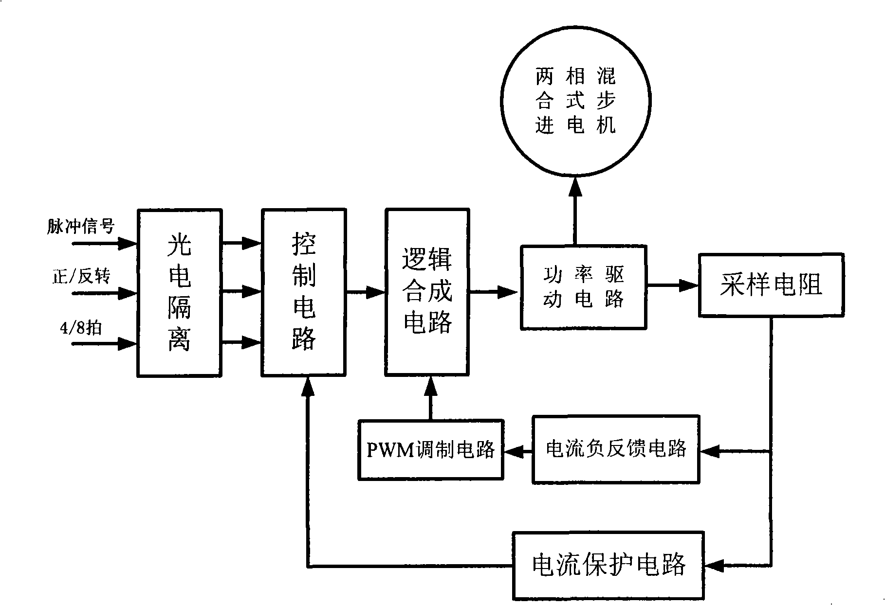
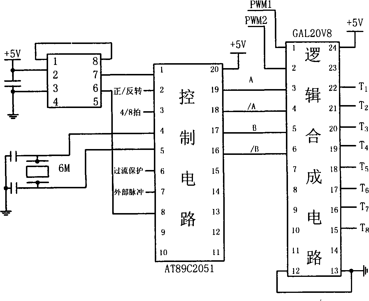
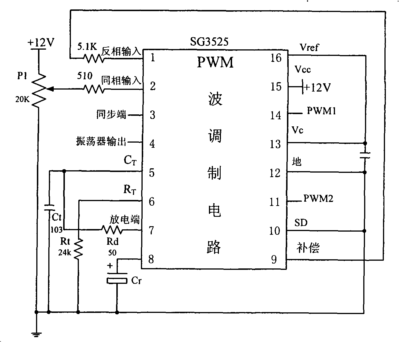
[0025] In this embodiment, the control circuit is mainly composed of a single-chip microcomputer AT89C2051. At the same time, in order to prevent the program from running away and effectively monitor the circuit, a watchdog circuit is used in the control circuit. The control circuit accepts external forward / reverse, pulse signals, 4 / 8 beat switching and overcurrent protection signals, which are input to the P3.0, P3.3, P3.1, and P3.2 ports of the microcontroller after photoelectric isolation. Output A, / A, B, / B 4-way signal. Among them, A and / A represent the positive and negative power bridge control signals of the A-phase winding, and B and / B represent the positive and negative power bridge control signals of the B-phase winding. The PWM wave modulation circuit adopts the integrated pulse width modulator SG3525 to realize the generation of the chopping current signal. Th...


PUM


Abstract

The invention relates to a driving system of a stepping motor with the current negative feedback, which is characterized in that: external signals pass through an optoelectronic isolating circuit and then are inputted into a control circuit. According to the detected signals, the control circuit generates four channels of input signals of A, / A, B and / B; the four channels of the signals, together with two channels of complementary and unipolar PWM waves which are generated by a PWM wave modulation circuit, enter a logic composite circuit, and then the logic composite circuit generates eight channels of outputs and the eight channels of the outputs are sent to a power driving circuit; the power driving circuit inputs control signals into the stepping motor; meanwhile, return signals on a sampling resistance respectively pass through a current negative feedback circuit to adjust the PWM wave modulation circuit, and pass through a current protection circuit to adjust the control circuit. The driving system of the invention has the advantages that a feedback element is added into the previous driving system of the stepping motor to ensure the steady phase current within a certain frequency ranges so as to realize the steady load capacity and more stable operation.

Description

technical field [0001] The invention relates to a stepping motor drive system with current negative feedback, which belongs to the field of electric engineering. As a device for driving and controlling stepper motors, it can drive and control steppers in a wide voltage range. Background technique [0002] When the stepper motor is running, when the frequency increases, the inductive reactance in the phase winding increases, thereby increasing the impedance value of the phase winding. The increase in frequency means that the speed also increases, and the increase in speed leads to an increase in the back electromotive force. These factors Combined, this results in a reduction in phase current, which leads to a reduction in the ability to carry the load. Therefore, it is necessary to increase the duty cycle of the PWM wave to keep the phase current at a stable value. [0003] In the past, the stepper motor controller needed to manually adjust the duty cycle of the PWM wave, ...

Claims


Application Information

Patent Timeline
Patent Type & Authority Applications(China)
IPC IPC(8): H02P8/22H02P8/12H02P8/14
Inventor 刘景林王帅夫韩英桃
Owner NORTHWESTERN POLYTECHNICAL UNIV
Learn More