Low speed heavy pressure vane pump for hydraulic bicycle

A bicycle and vane pump technology, which is applied to vehicle gearboxes, pumps, pump components, etc., can solve problems such as inconvenient operation, strict technical requirements, and power mismatch, and achieve easy installation and disassembly, simple process and materials, and starting performance Good results

Inactive Publication Date: 2008-10-22
邵锐勋 +1
View PDF1 Cites 19 Cited by
  • Summary
  • Abstract
  • Description
  • Claims
  • Application Information

AI Technical Summary

Problems solved by technology

But also there are many fundamental deficiencies in the direct use of existing vane pumps in hydraulic bicycles:
Although there are some innovations to meet the low-speed requirements of the vane oil pump at a minimum speed of 5km/h when riding a two-wheeled vehicle at a low speed of 15-30R/min, there is still the problem of extremely low volumetric efficiency (close to zero) at high pressure (4mpa).
[0004]2. Power mismatch
However, all kinds of transmissions have common disadvantages: complex structure, inconvenient operation, small speed range, and the transmission cannot reasonably match the output of the human body (N human body power = F pedal output. V vehicle speed)
However, when the oil pressure of the bicycle rises rapidly to 4-6Mpa in a relatively short time, distance, and starting (vehicle speed is 0 to rated speed 25km/h), due to the accumulation of the maximum clearance of the blade and the oil distribution window to 0.04-0.06mm, then Due to the force of the screws connecting the left and right housings and the elastic deformation of the housings, the gap between the oil distribution plate and the blades that are integrated with the left and right housings will further increase, and the internal leakage of the blades will increase, and the pressure generated by the oil pump will f

Method used


Image

  • Low speed heavy pressure vane pump for hydraulic bicycle
  • Low speed heavy pressure vane pump for hydraulic bicycle
  • Low speed heavy pressure vane pump for hydraulic bicycle

Examples


Embodiment Construction

[0044] The present invention will be described in further detail below in conjunction with accompanying drawing (embodiment):

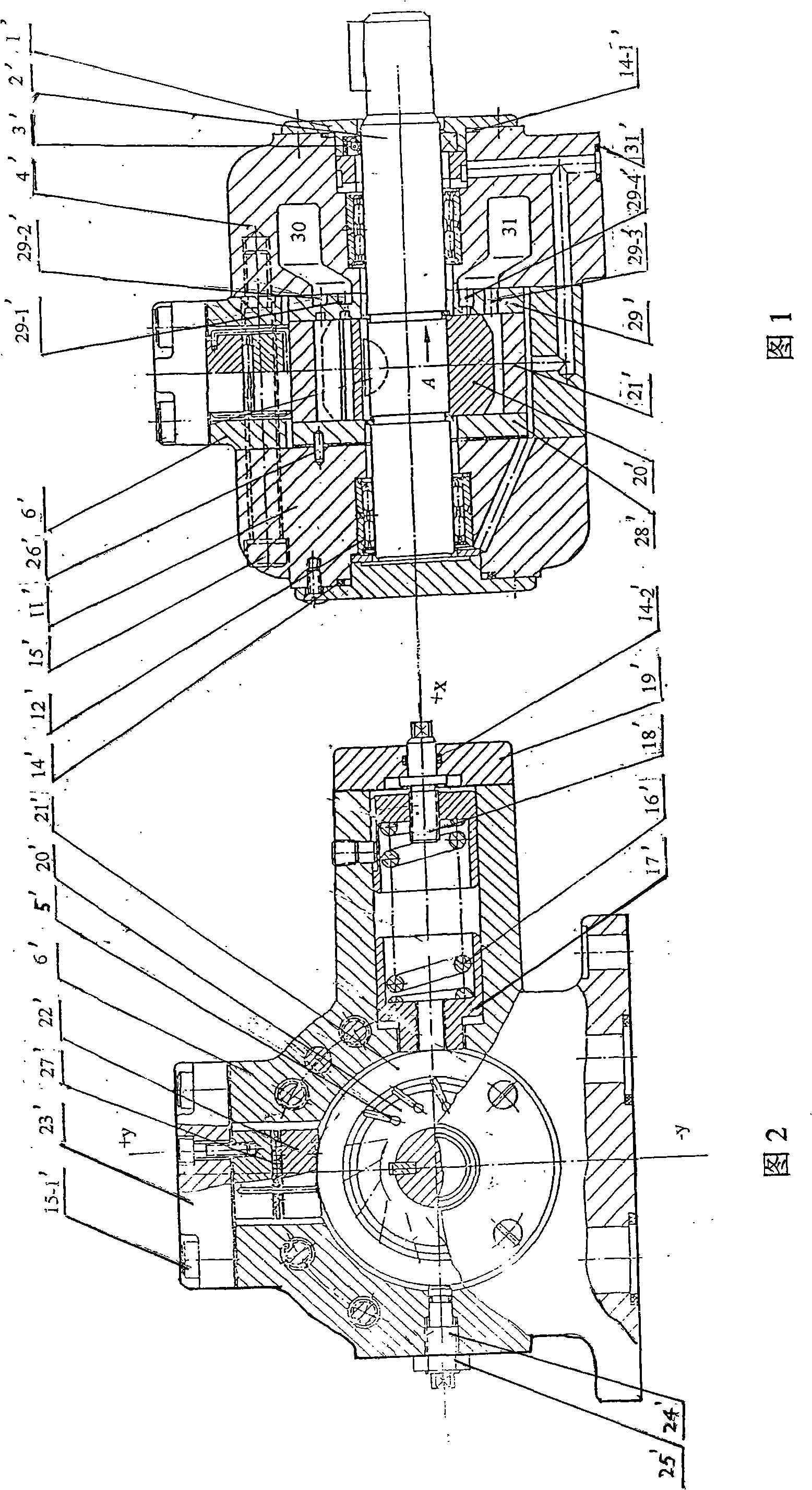
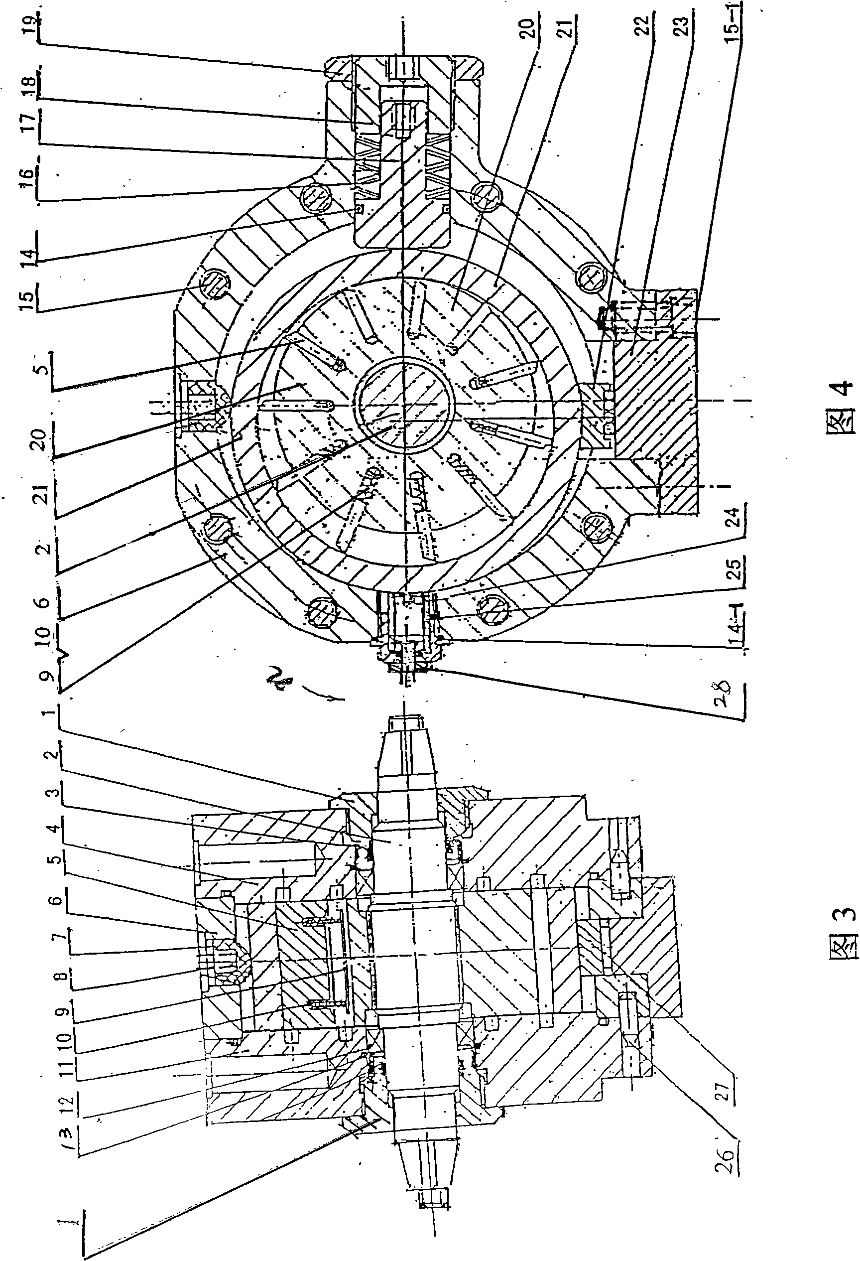
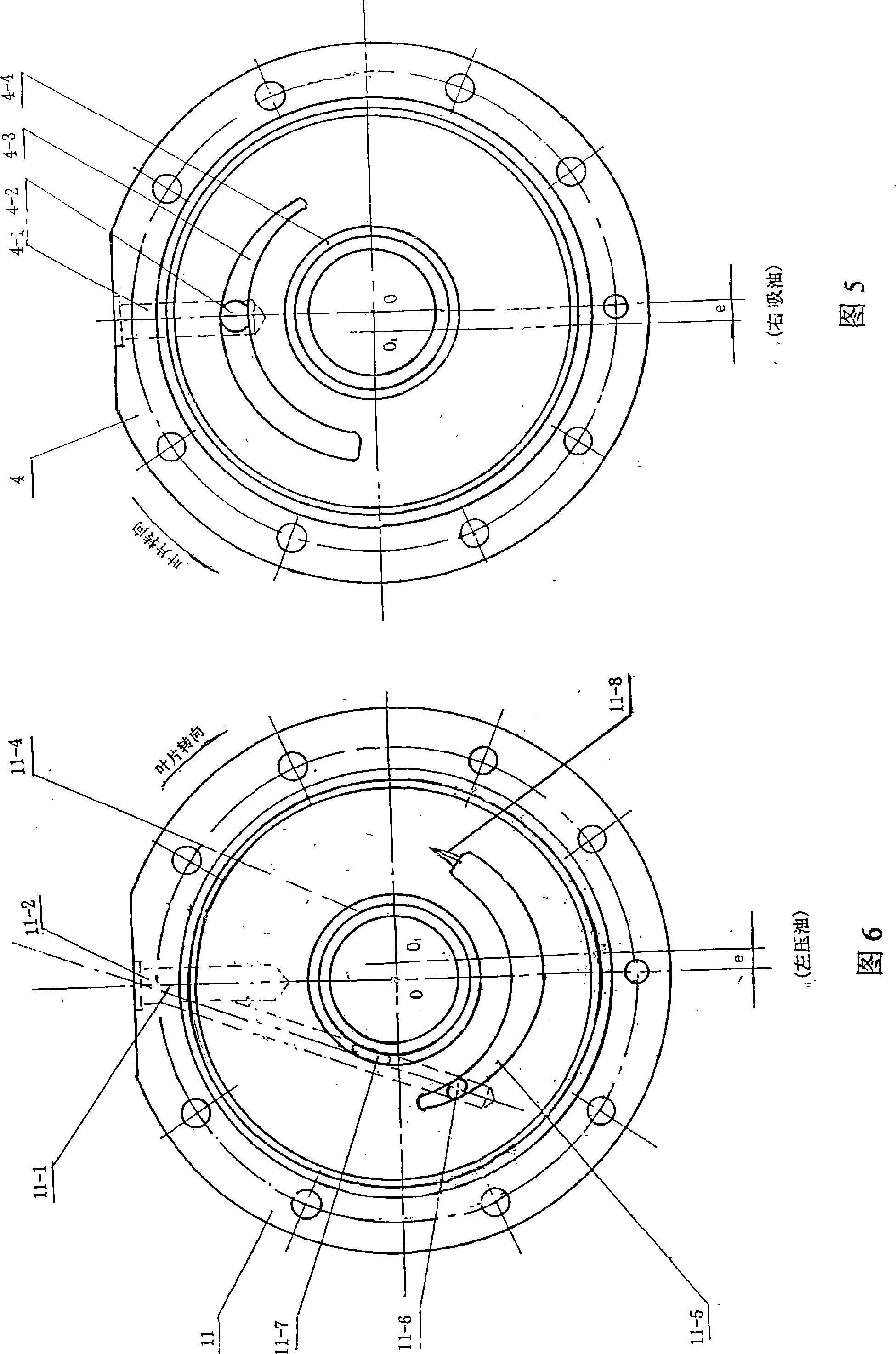
[0045] Referring to Figures 3 to 9, the present invention includes an end cover 1, a main shaft 2, a skeleton seal 3, a right housing 4, blades 5, a middle housing 6, a positioning guide sleeve 7, a positioning spring 8, a blade bracket 9, and a blade spring 10 , left housing 11, bearing 1 2, collar 1 3, "O" type sealing ring 14, 14-1, screw 15, pressure limiting spring 16, spring seat 17, adjusting nut 18, lock nut 19, rotor 20, Stator 21, slider 22, cover plate 23, flow adjustment screw 24, sealing ring 25, positioning pin 26, needle roller 27, lock nut 28, etc. The present invention is a "three-piece" structure, which is composed of three pieces, namely the left casing 11, the right casing 4 and the middle casing 6. The rotor 20, the stator 21, the pressure limiting spring 16, the adjustment nut 18, the lock nut 19, the flow adjustment screw 24, t...


PUM


Abstract

The invention discloses a low-speed high-pressure vane pump for hydraulic bicycles. The invention comprises an end cover, a principal axis, a framework oil seal, a right casing, a blade, a middle casing, a left casing, a bearing, an O-shaped sealing ring, a bolt, a pressure-limiting spring, a spring seat, a regulating nut, a side end cover, a rotor, a stator, a slide block, a cover plate, a flow adjusting screw, a sealing ring, a lock nut and a needle roller. The invention is characterized in that: a vane groove is arranged in the rotor, a vane spring and a vane bracket are arranged in the vane groove, the vane bracket is positioned by the vane spring, the blade is arranged in the vane groove of the rotor, one end of the blade presses the vane spring, while the other end clings to the inner surface of the stator. The low-speed high-pressure vane pump for the hydraulic bicycles has the advantages of reasonable structure, light self-weight, small bulk, high efficiency, low cost, labor conservation and rapidness, which is adopted to be matched with all wheel diameters of bicycles and has the function of pressure servo variation.

Description

technical field [0001] The invention relates to a vane pump, in particular to a low-speed and high-pressure vane pump for hydraulic bicycles. Background technique [0002] The power of existing vane oil pumps all considers the industrial use of products, such as machine tools, hydraulic machines, excavators, automobiles, etc., the power is generally 1 kilowatt to tens of kilowatts, and the rotating speed is 1000~1500 rpm. Parts, materials, structure, weight, installation, appearance, etc. are all oriented from the perspective of industrial machinery and tools as a whole, and are not suitable for civilian use, as shown in Figure 1 and Figure 2. In the figure, 1' is the end cover, 2' is the main shaft, 3' is the skeleton oil seal, 4' is the right shell, 5' is the vane, 6' is the middle shell, 11' is the left shell, 12' is the bearing, 14', 14-1', 14-2' are "O" seal rings, 15', 15-1' are screws, 16' are pressure limiting springs, 17' are spring seats, 18' are adjusting screws,...

Claims


Application Information

Patent Timeline
IPC IPC(8): F04C2/344F04C15/00B62M19/00
CPCF04C2/3442F01C21/0845F04C14/223
Inventor 邵锐勋李焕萍
Owner 邵锐勋
Why Eureka
Try Eureka