Liquid crystal display panel, LCD display and method for producing same

A liquid crystal display panel and liquid crystal display technology, applied in the direction of static indicators, instruments, etc., can solve the problems of liquid crystal display brightness decrease, affect the picture quality, and decrease the overall transmittance, so as to improve the overall screen brightness and enhance the overall penetration rate effect

Inactive Publication Date: 2008-10-22
INNOLUX CORP
View PDF0 Cites 11 Cited by
  • Summary
  • Abstract
  • Description
  • Claims
  • Application Information

AI Technical Summary

Problems solved by technology

[0014] However, since the transmittance of the second sub-pixel 114 is lower than that of the first sub-pixel 112, the overall transmittance of the conventiona

Method used


Image

  • Liquid crystal display panel, LCD display and method for producing same
  • Liquid crystal display panel, LCD display and method for producing same
  • Liquid crystal display panel, LCD display and method for producing same

Examples


Embodiment Construction

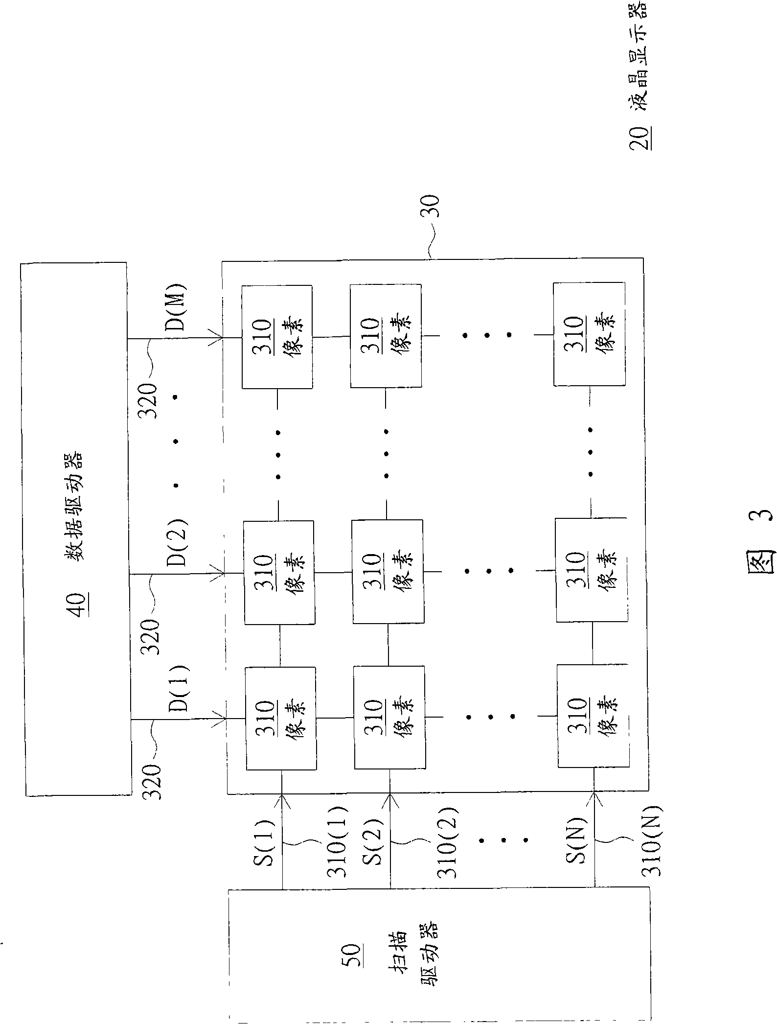
[0068] Schematic diagram of an LCD display

[0069] Please refer to FIG. 3 , which shows a schematic diagram of a liquid crystal display. The liquid crystal display 20 includes a liquid crystal display panel 30 , a data driver 40 and a scan driver 50 . The liquid crystal display panel 30 includes a plurality of pixels 310, data lines 320, and scan lines 330(1) to 330(N). The data driver 40 is coupled to the data line 320 and outputs corresponding data signals D( 1 ) to D(M) to the pixels 310 through the data line 320 . The scan driver 50 is coupled to the scan lines 330(1) to 330(N), and outputs scan signals S(1) to S(N) through the scan lines 330(1) to 330(N) to sequentially enable each Column pixels 310 .

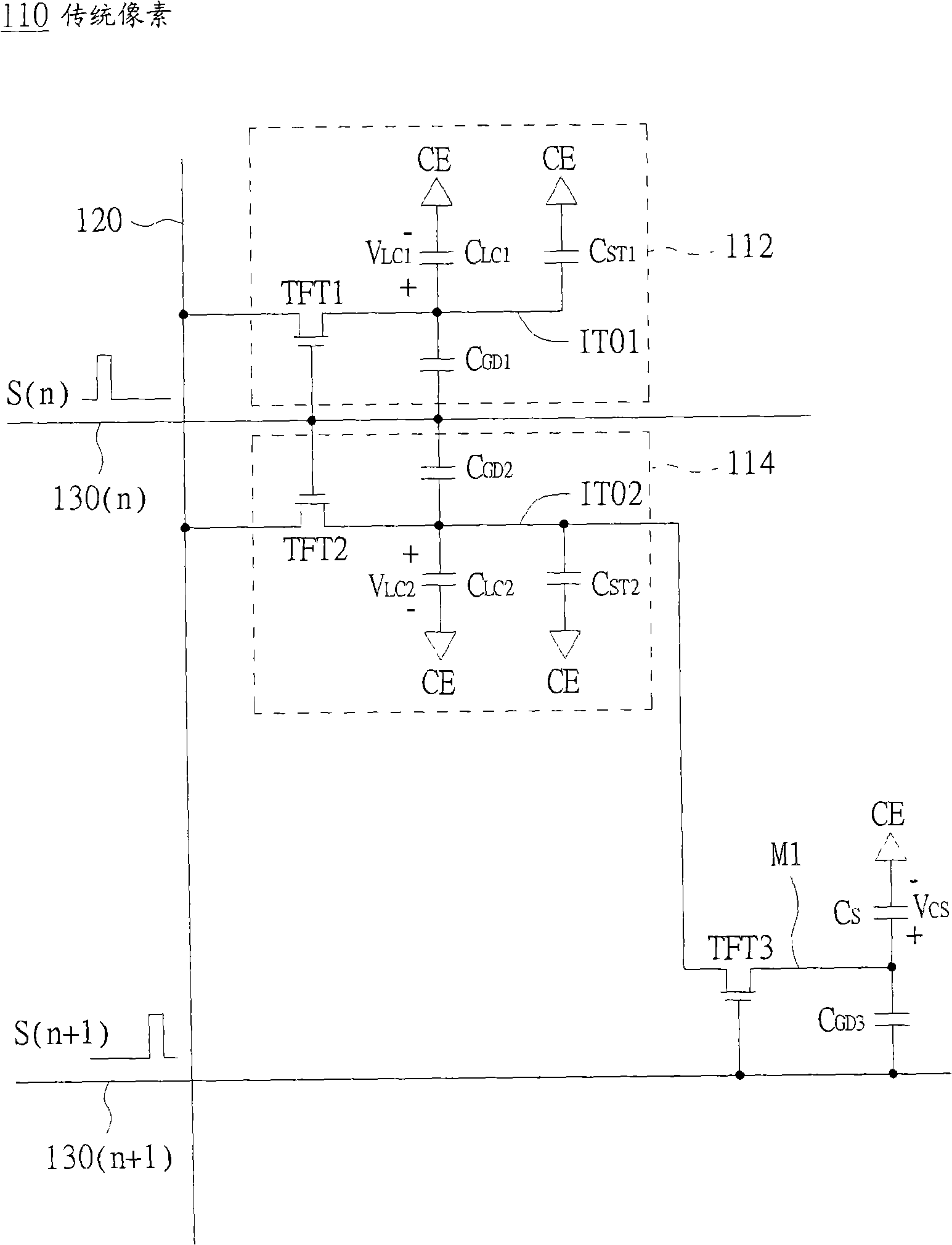
[0070] Equivalent circuit diagram of a pixel

[0071] For the convenience of description, the first switch Q1, the second switch Q2 and the third switch Q3 in the following pixel 310 are described as thin film transistors (Thin Film Transistor, TFT) as an example,...


PUM


Abstract

The invention provides a liquid crystal display panel, a liquid crystal display and a method for driving the same. The liquid crystal display panel comprises a data wire, a first scanning beam, a second scanning beam and a pixel, wherein, the second scanning beam is the next scanning beam adjacent to the first scanning beam; the pixel comprises a first sub-pixel, a second sub-pixel, a third switch, an auxiliary capacitor and a feedback capacitor; moreover, the first sub-pixel and the second sub-pixel are respectively comprise a first switch and a second switch; input ends of the first switch and the second switch are coupled with the data wire, controlled ends of the first switch and the second switch are coupled with the first scanning beam; and an output end of the third switch is coupled with a common electrode through the auxiliary capacitor and is coupled with an output end of the first switch through the feedback capacitor.

Description

technical field [0001] The invention relates to a liquid crystal display panel, a liquid crystal display and a driving method thereof, and in particular to a liquid crystal display panel with low color shift, a liquid crystal display and a driving method thereof. Background technique [0002] Since the retardation value (Retardation) generated by the incident light at different angles in the liquid crystal layer is different, when the viewing angle is different, the refraction coefficient of the light is different, resulting in a different transmittance. Therefore, different viewing angles will cause different brightness of the displayed light. When different colors of light (such as red light, green light and blue light) are mixed with different brightness examples when viewed from the front and side, there will be a color shift phenomenon (Color Shift) in which the colors displayed by the front view and the side view are different. . [0003] In order to improve the colo...

Claims


Application Information

Patent Timeline
IPC IPC(8): G02F1/133G09G3/36G09G3/20
Inventor 陈建宏谢志勇
Owner INNOLUX CORP
Why Eureka
Try Eureka