Retina cell microscopic imaging system using shearing interfere phase contrast technique

A retinal cell and microscopic imaging technology, applied in the direction of ophthalmoscope, can solve problems such as poor flexibility, and achieve the effect of flexible unit position and unlimited illumination aperture

Inactive Publication Date: 2008-10-29
江阴龙跃信息科技有限公司 +1
View PDF4 Cites 2 Cited by
  • Summary
  • Abstract
  • Description
  • Claims
  • Application Information

AI Technical Summary

Problems solved by technology

However, there are strict position requirements when u

Method used


Image

  • Retina cell microscopic imaging system using shearing interfere phase contrast technique

Examples


Embodiment

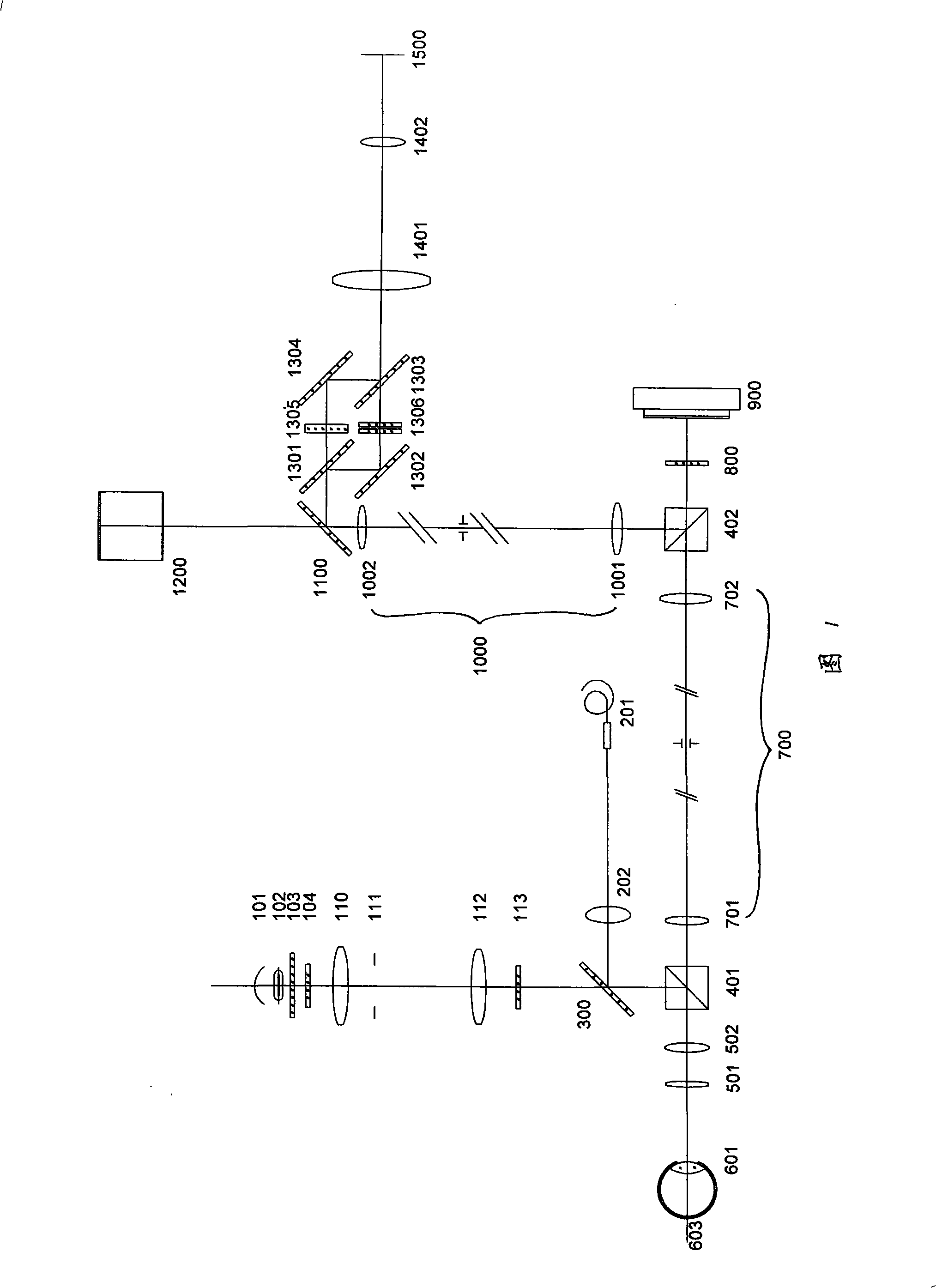
[0015] Embodiment: As shown in Figure 1, a retinal cell microscopic imaging system using shearing interference phase contrast technology, in its imaging optical system, is provided with a phase-type transparent retinal structure converted into a corresponding light intensity Change the image of the interference contrast optical unit.

[0016] The interference phase contrast optical unit includes two total reflection mirrors 1302 , 1304 , two half mirrors 1301 , 1302 , a compensation plate 1305 and an optical wedge group 1306 .

[0017] Half reflection half mirror 1301, total reflection mirror 1302, total reflection mirror 1304 and half reflection half mirror 1303 are rectangular four vertex positions and are arranged, wherein two total reflection mirrors 1302, 1304 are mutually diagonally arranged, two half reflection half mirrors The lenses 1301 and 1302 are arranged diagonally to each other. The compensation plate 1305 is located between the half mirror 1301 and the total r...


PUM


Abstract

The present invention discloses a retina cell microscopic imaging system which uses a shearing interference phase contrast technology. An imaging optical system is provided with an interference phase contrast optical unit which converts phase type transparent retina structure into a corresponding image with light intensity change. The retina cell microscopic imaging system comprises two pieces of holophotes (1302 and 1304), two pieces of half-reflecting and half-transmitting mirrors (1301 and 1302), a compensating plate (1305) and an optical wedge set (1306). Two pieces of the holophotes (1302 and 1304) and two pieces of the half-reflecting and half-transmitting mirrors (1301 and 1302) are arranged at the positions of four peaks shaped as rectangle. The compensating plate (1305) is arranged between the half-reflecting and half-transmitting mirror (1301) and the holophote (1304). The optical wedge set (1306) is arranged between the holophote (1302) and a half-reflecting and half-transmitting mirror (1303). The retina cell microscopic imaging system of the present invention can clearly reflect the structural detail on the retina, and a formed retina image has third dimension and can change interference color; illumination aperture is not limited; the periphery is not provided with false band; the position of the interference phase contrast optical unit can be arranged flexibly.

Description

technical field [0001] The invention relates to a retinal cell microscopic imaging system, in particular to a retinal cell microscopic imaging system using shear interference phase contrast technology. Background technique [0002] The interference phase contrast technology mentioned in the patents CN99115051.1, CN99115052.X, CN99115053.8 and CN99115054.6 of the Institute of Optoelectronic Technology of the Chinese Academy of Sciences is realized by a phase contrast plate. In principle, the interference involved in the phase contrast plate technology is the interference between the background light from the phase body and the diffracted light, which is the beam interference based on the theory of Fourier optical spectrum. However, there are strict position requirements when using phase contrast plates, and the flexibility is poor. Contents of the invention [0003] The object of the present invention is to provide a retinal cell microscopic imaging system using shearing i...

Claims


Application Information

Patent Timeline
IPC IPC(8): A61B3/13
Inventor 周明宝张运海任建伟
Owner 江阴龙跃信息科技有限公司
Why Eureka
Try Eureka