

Apery robot distributed dual-bus motion control system
A motion control system and humanoid robot technology, applied in the directions of comprehensive factory control, comprehensive factory control, electrical program control, etc., can solve the problem that it is difficult to meet the higher real-time requirements of the humanoid robot system, and the CAN bus data transmission speed is limited. and other problems to achieve high real-time performance, reduce data volume, and reduce data volume.
- Summary
- Abstract
- Description
- Claims
- Application Information
AI Technical Summary
Problems solved by technology
Method used
Image

Examples
Embodiment 1
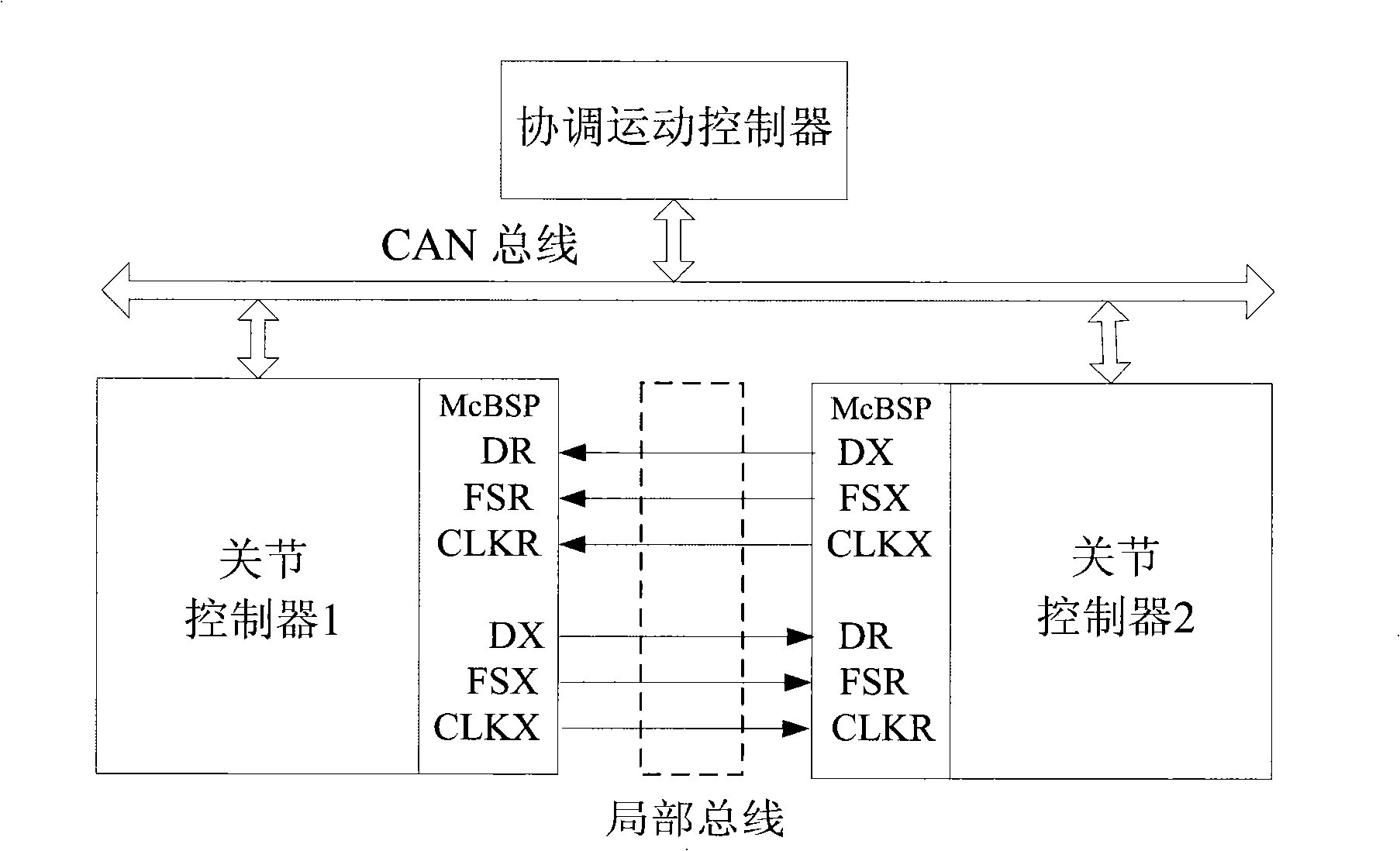
[0015] Example 1 as figure 2 shown. figure 2 Nakamoto motion control system consists of coordinated motion controller, CAN bus, local bus, joint controller 1 and joint controller 2. The coordinated motion controller is connected to the joint controllers 1 and 2 through the CAN bus, and the joint controllers 1 and 2 are interconnected through the local bus. The local bus is implemented through the McBSP interface on joint controllers 1 and 2. McBSP is a multi-channel buffered serial interface that can send and receive 8 / 16 / 32-bit serial data synchronously. Both reception and transmission use independent clock and frame signals, whose source, frequency and polarity can be programmed by the user, and support up to 128 channels for transmission and reception. McBSP includes a data flow path and a control path, and is connected to external devices through 6 signal lines. Data is sent through the sending pin DX and received through the receiving pin DR. The clock and frame sy...
Embodiment 2
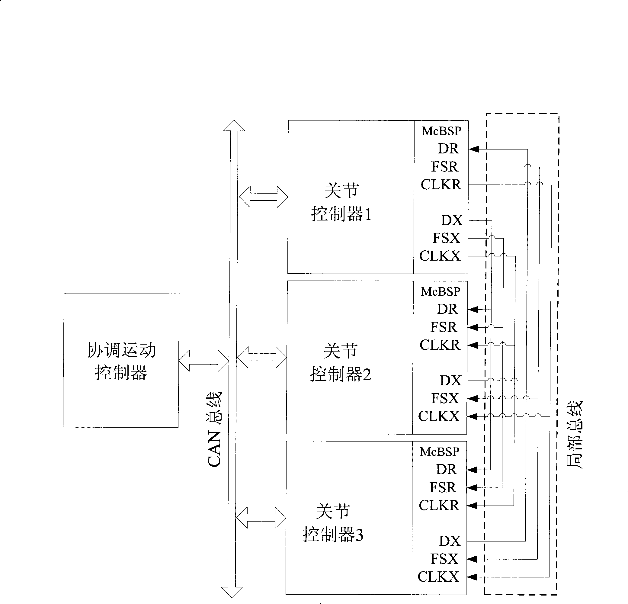
[0016] Example 2 as image 3 shown. image 3 Nakamoto motion control system consists of coordinated motion controller, CAN bus, local bus, joint controller 1, joint controller 2 and joint controller 3. The coordinated motion controller is connected to all joint controllers 1, 2 and 3 through the CAN bus, and the joint controllers 1, 2 and 3 are interconnected through the local bus. The local bus is still implemented using the McBSP interface on the joint controller. Set joint controller 1, which has a relatively light computational load, as the master, and set all other joint controllers 2 and 3 as slaves. Connect the pins DX, CLKX and FSX related to sending data on the main joint controller 1 to the pins DR, CLKR and FSR related to receiving data on joint controllers 2 and 3 respectively, and connect the pins on joint controllers 2 and 3 to The pins DX, CLKX and FSX related to sending data are respectively connected to the pins DR, CLKR and FSR related to receiving data on...
Embodiment 3
[0017] Example 3 as Figure 4 shown. Figure 4 Nakamoto motion control system consists of coordinated motion controller, CAN bus, local bus, joint controller 1, joint controller 2 and joint controller 3. The coordinated motion controller is connected to the joint controllers 1, 2 and 3 through the CAN bus, and the joint controllers 1, 2 and 3 are interconnected through the local bus. The local bus is still implemented using the McBSP interface on the joint controller. In terms of hardware, connect the pins related to sending data on joint controller 1 to the pins related to receiving data on joint controller 2, and connect the pins related to sending data on joint controller 2 to joint controller 3 respectively. Connect the pins related to receiving data on the joint controller 3 to the pins related to sending data on the joint controller 3 and the pins related to receiving data on the joint controller 1 to form a ring topology network. If you need to connect more joint con...
PUM
 Abstract
Description
Claims
Application Information