
Design method of real beam forming machine

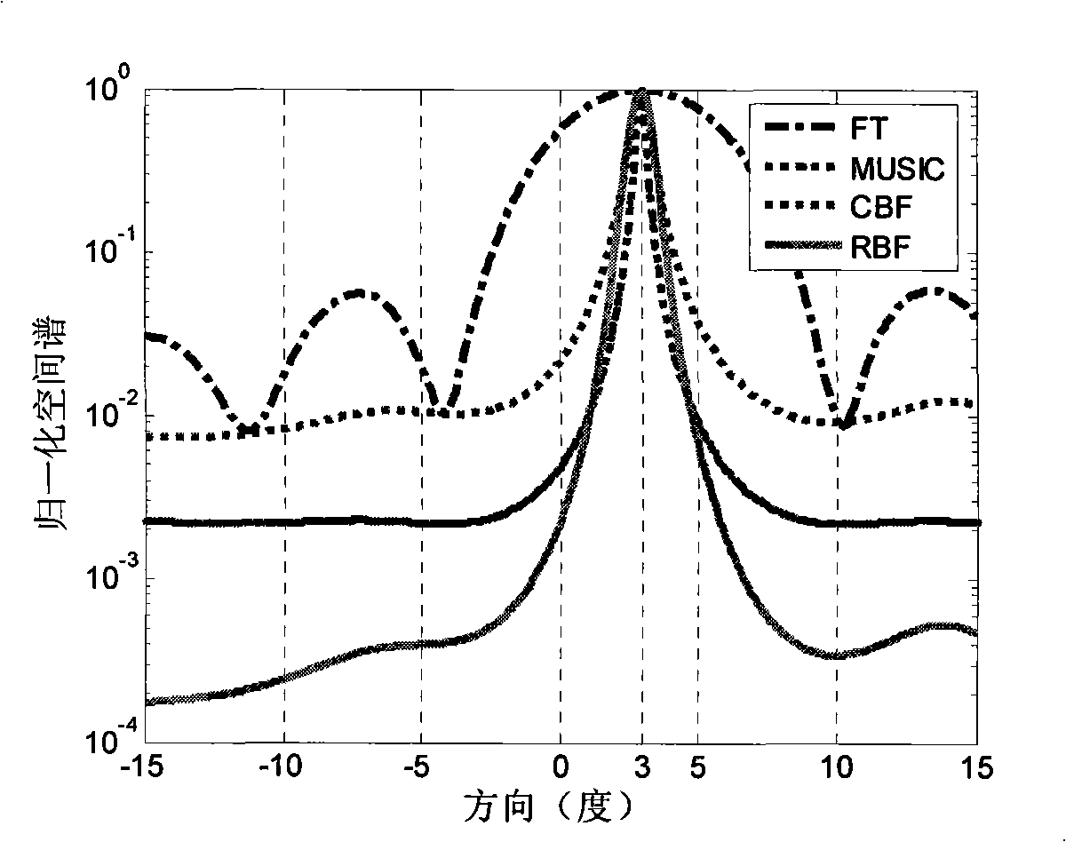
A design method and real beam technology, applied in the field of signal processing, can solve the problem of beamformer direction resolution deterioration and other problems, and achieve the effects of reduced real number calculation, low side lobe level, and high resolution

Inactive Publication Date: 2008-10-29
UNIV OF ELECTRONIC SCI & TECH OF CHINA
View PDF0 Cites 10 Cited by
  • Summary
  • Abstract
  • Description
  • Claims
  • Application Information

AI Technical Summary

Problems solved by technology

However, since the ideal beamformer is related to the true value of the autocorrelation matrix, when the number of array snapshots is small and the signal-to-noise ratio is low, the sample autocorrelation matrix will inevitably be greatly affected by noise, resulting in beamforming Orientation resolution of the sensor deteriorates

Method used


Image

  • Design method of real beam forming machine
  • Design method of real beam forming machine
  • Design method of real beam forming machine

Examples


Embodiment Construction

[0033] Specific embodiments of the present invention will be described below in conjunction with the accompanying drawings.

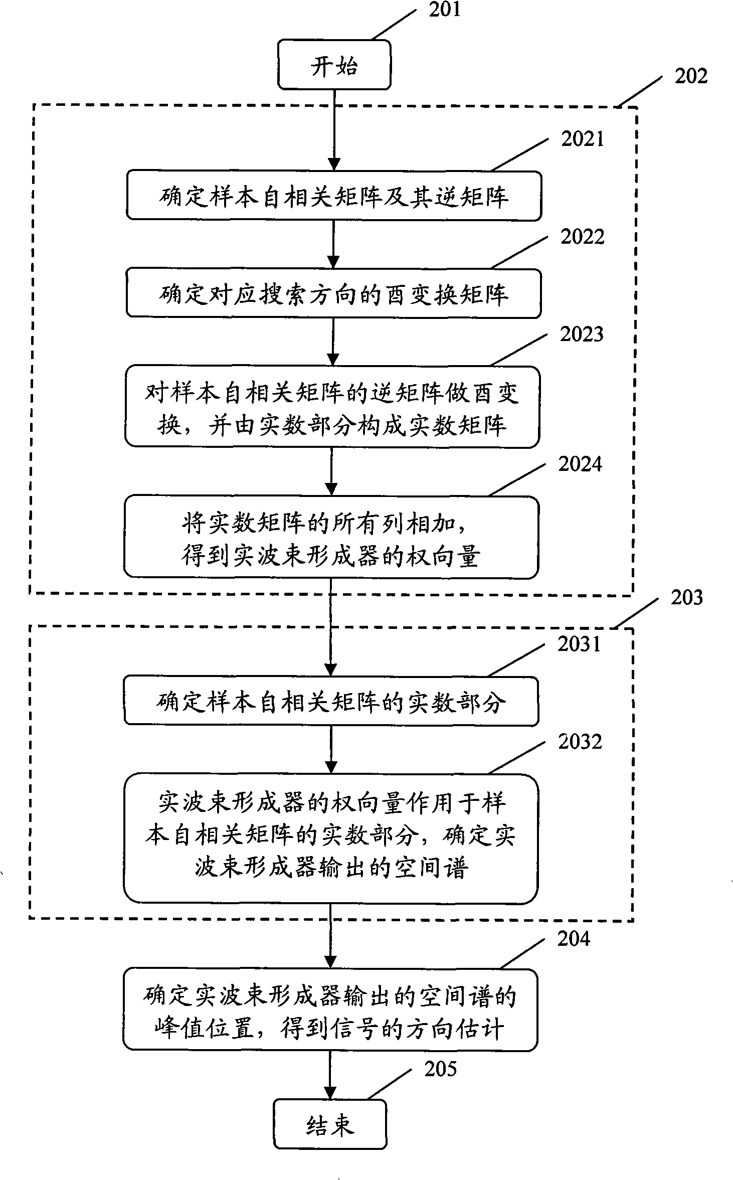
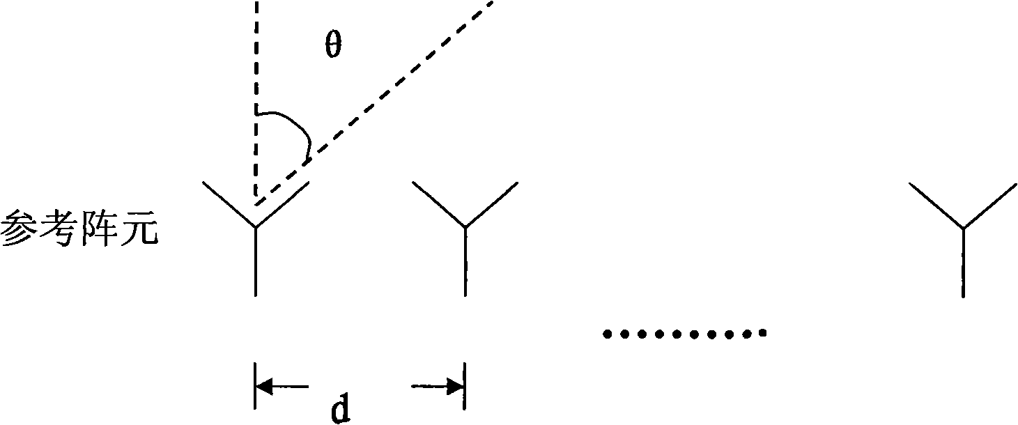
[0034] Determining the sample autocorrelation matrix from the array received data, R = 1 N Σ t = 1 N X ( t ) X H ( t ) The array is not limited by shape, including uniform line arrays, non-uniform line arrays, circular arrays, randomly distributed arrays, and the like. as figure 2 The uniform linear array shown is an example, the number of array elements is M, and the distance between adjacent array elements is d. Suppose there are D incoherent narrowband signals s in the space k (t), k=1, 2, ..., D, arrive at this line array, and the included angle with the l...


PUM


Abstract

The invention relates to a design method for a real beam former. A real number weight vector of the real beam former is designed by utilizing two different orthogonality relations so as to cause the output of the real beam former to appear obvious local maximum along the corresponding signal direction, thus finishing the forming of the real beam with lower side lobe level and higher direction resolution to weak signals and coherent signals. The method comprises the following steps: an array received data is used for determining a sample autocorrelation matrix and an inverse matrix thereof; a unitary transformation matrix corresponding to the searching direction is determined and unitary transformation is carried out, and only the real number part of a unitary transformation result is taken; the weight vector of the real beam former is obtained according to the sum of the column vector of the matrix of the real number part of the unitary transformation result. The weight vector of the real beam former is acted on the real number part of the sample autocorrelation matrix, and the spatial spectrum of the real beam former is determined: the direction estimation of a corresponding signal is obtained by searching the peak position of the spatial spectrum, and the forming of the real beam is finished. The method provides a new method for array signal processing, with remarkable effect and significant meaning.

Description

Technical field [0001] The invention belongs to signal processing, relates to array signal beam forming technology, in particular to a design method of a high-resolution real beam former. Background technique [0002] In the array signal beamforming technology, the active / passive direction finding system needs to use high-resolution technology to separate the signals in the direction in order to use the signals received by the array with limited aperture for multi-target direction finding. However, the directional resolution of the classical spatial Fourier transform method is limited by the Rayleigh limit, and the Rayleigh limit is only determined by the size of the array aperture. The method of improving the signal-to-noise ratio breaks the Rayleigh limit. In the existing array direction finding technology, Capon's beamforming method and typical subspace methods, such as multiple signal classification method (MUSIC, MUltiple SIgnals Classification) are usually used to rea...

Claims


Application Information

Patent Timeline
IPC IPC(8): G01S7/02G01S13/00
Inventor 万群杨万麟窦衡沈晓峰杨瑞明
Owner UNIV OF ELECTRONIC SCI & TECH OF CHINA
Learn More