Silicon capacitor microphone

A technology of microphones and silicon capacitors, applied in the field of microphones, can solve the problems of limited increase in the rear cavity, difficulty in manufacturing silicon microphone products, and increased product height.

Active Publication Date: 2008-10-29
WEIFANG GOERTEK MICROELECTRONICS CO LTD
View PDF1 Cites 24 Cited by
  • Summary
  • Abstract
  • Description
  • Claims
  • Application Information

AI Technical Summary

Problems solved by technology

[0004] However, this design has a very limited increase in the rear cavity and a very small contribution to performance improvement; moreover, this design will greatly increase the thickness of the circuit boar

Method used


Image

  • Silicon capacitor microphone
  • Silicon capacitor microphone
  • Silicon capacitor microphone

Examples


Embodiment 1

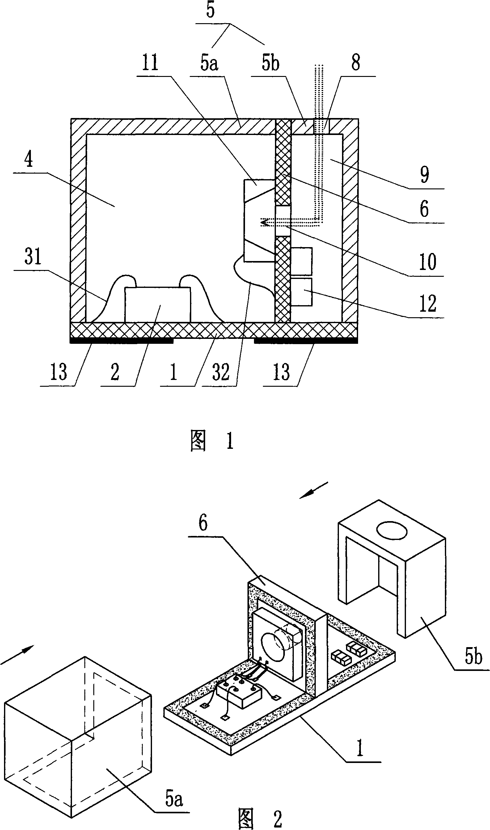
[0020] Embodiment 1: As shown in Figure 1 and Figure 2, the silicon capacitor microphone includes: a rectangular first circuit board 1, a plurality of pads 13 are arranged on the lower side of the first circuit board 1, and an integrated circuit 2 is installed on the upper side, integrated On the circuit 2, a gold wire 31 is connected to the first circuit board 1; on one side of the integrated circuit 2, a rectangular second circuit board 6 is installed on the first circuit board 1, and the second circuit board 6 and the first circuit board 1 The direction is vertical and mechanically connected together and part of the circuit is electrically connected. On the second circuit board 6, a MEMS acoustic chip 11 is installed on the side facing the integrated circuit 2, and a gold wire 32 is connected to the second circuit board 6 on the MEMS acoustic chip 11. There is an inner acoustic hole 10 on the bottom surface of the MEMS acoustic chip 11, and electronic components 12 such as c...

Embodiment 2

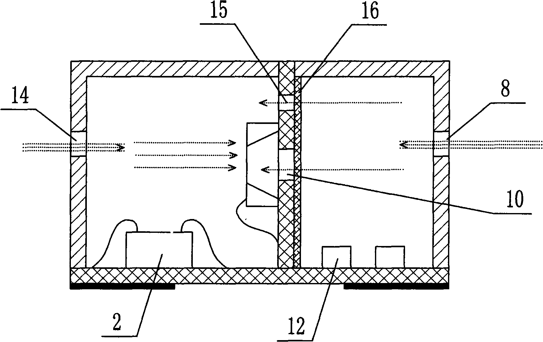
[0030] Embodiment two: if image 3As shown, the silicon condenser microphone of this embodiment is a unidirectional silicon condenser microphone. Compared with the embodiment 1, the adjustment of this case is: the first housing 5a and the second housing 5b are respectively provided with external sound holes 14 and 8; on the second circuit board 6, except the inner acoustic hole 10 below the MEMS acoustic chip 11, a cavity-connected acoustic hole 15 is also provided around the MEMS acoustic chip 11; on the second circuit board 6 relative to the MEMS acoustic One side of the chip 11 is affixed with an acoustic resistance 16, and the acoustic resistance 16 covers all sound holes set on the second circuit board 6; no capacitor 12 is installed on the second circuit board 6 relative to the side of the MEMS acoustic chip 11 and other parts, and these parts are installed on the first circuit board 1. There are no components such as capacitors on the side of the second circuit board 6...


PUM


Abstract

The invention discloses a silicon capacitor microphone which comprises a first circuit board provided with an external bonding pad, a second circuit board arranged on the first circuit board vertically, an MEMS acoustic chip arranged on the second circuit board, an internal sound hole which can act on the MEMS acoustic chip by sound waves and is arranged on the second circuit board on the position of the MEMS acoustic chip, a shell which is adhered to the first circuit board and the second circuit board and forms two sealed cavities, an external sound hole arranged on the external wall of one or two of the sealed cavities for receiving external audio signals, and an electron component arranged on the first circuit board or/and the second circuit board. Therefore, the volume of the back cavity of the silicon capacitor microphone is increased to a large extent, the area of the silicon capacitor microphone is reduced greatly, the installation positions of the internal parts of the silicon capacitor microphone are more flexible, and the functions of a directional microphone can be realized easily on the base of the structure.

Description

technical field [0001] The invention relates to a microphone, in particular to a silicon condenser microphone with a new packaging structure. Background technique [0002] In recent years, with the continuous reduction in volume and higher performance of electronic products such as mobile phones and notebooks, the supporting electronic components are also required to be continuously reduced in size and improved in performance and consistency. In this context, many new products have been launched in the field of microphone products as one of the important parts, and the silicon condenser microphone, which is realized in batches using semiconductor manufacturing and processing technology, is the representative product among them. The key design content of the silicon condenser microphone is the packaging technology, and the cost ratio of the packaging is relatively high. Therefore, there have been many patents on the packaging technology of the silicon condenser microphone rec...

Claims


Application Information

Patent Timeline
IPC IPC(8): H04R19/01H04R19/04
CPCH01L2224/48091H01L2924/3025H01L2924/1461H04R19/005H04R1/04H01L2924/00014H01L2924/00
Inventor 党茂强
Owner WEIFANG GOERTEK MICROELECTRONICS CO LTD
Why Eureka
Try Eureka