Shuttering component

A technology for formwork components and components, which is applied in the field of formwork components, and can solve problems such as inability to bear and transmit force on cast-in-place concrete hollow floors, damage to formwork components, poor overall strength and stiffness of formwork components, etc.

Inactive Publication Date: 2008-11-05
湖南邱则有专利战略策划有限公司
View PDF1 Cites 3 Cited by
  • Summary
  • Abstract
  • Description
  • Claims
  • Application Information

AI Technical Summary

Problems solved by technology

However, there is no reinforcing structure in the formwork components in this floor slab, the overall strength and rigidity of the formwork components are poor, and the phenomenon of damage to the formwo

Method used


Image

  • Shuttering component
  • Shuttering component
  • Shuttering component

Examples


Embodiment Construction

[0050] The present invention will be further described below in conjunction with the accompanying drawings and embodiments.

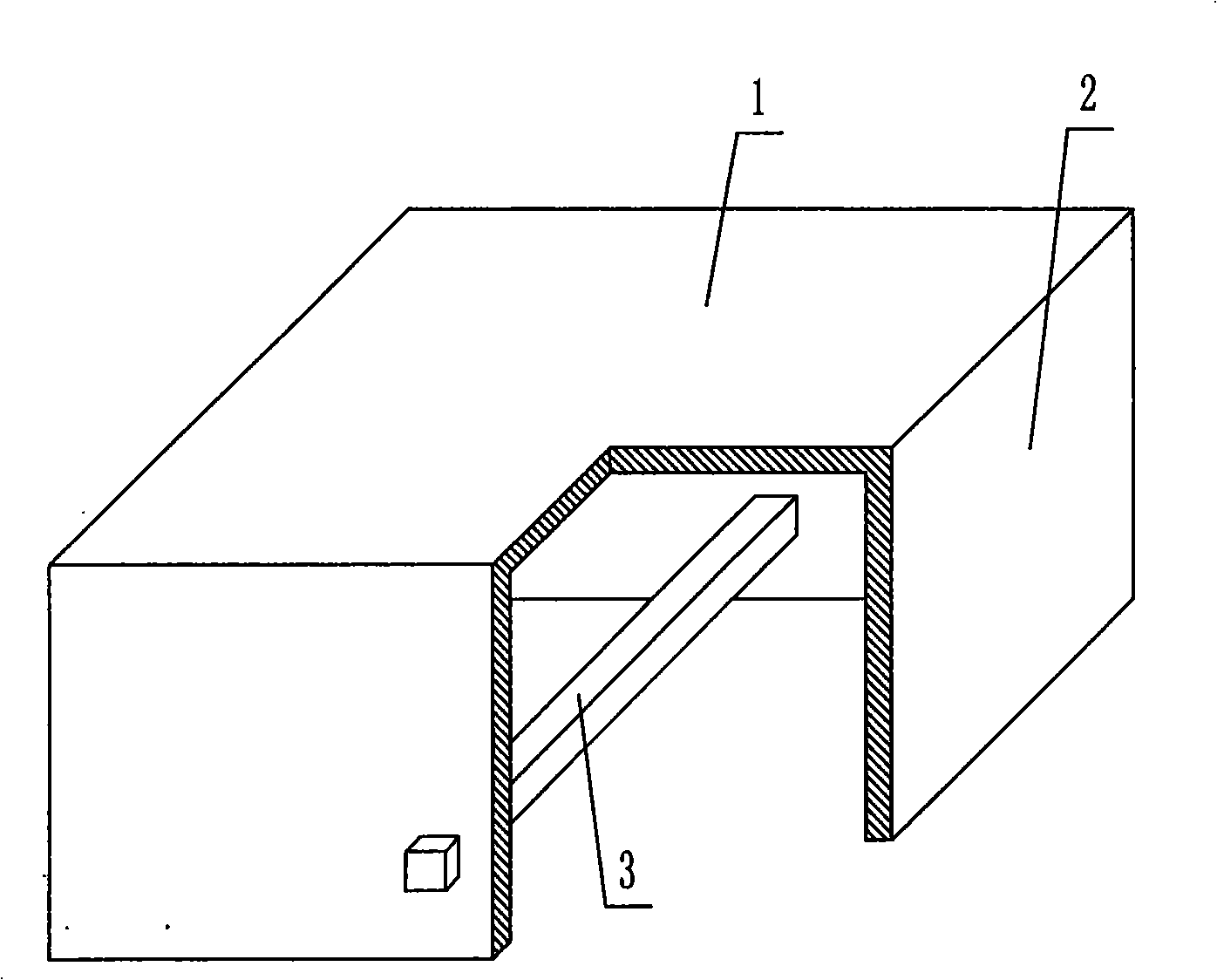
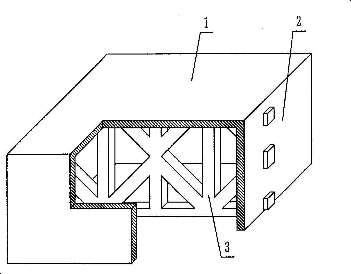
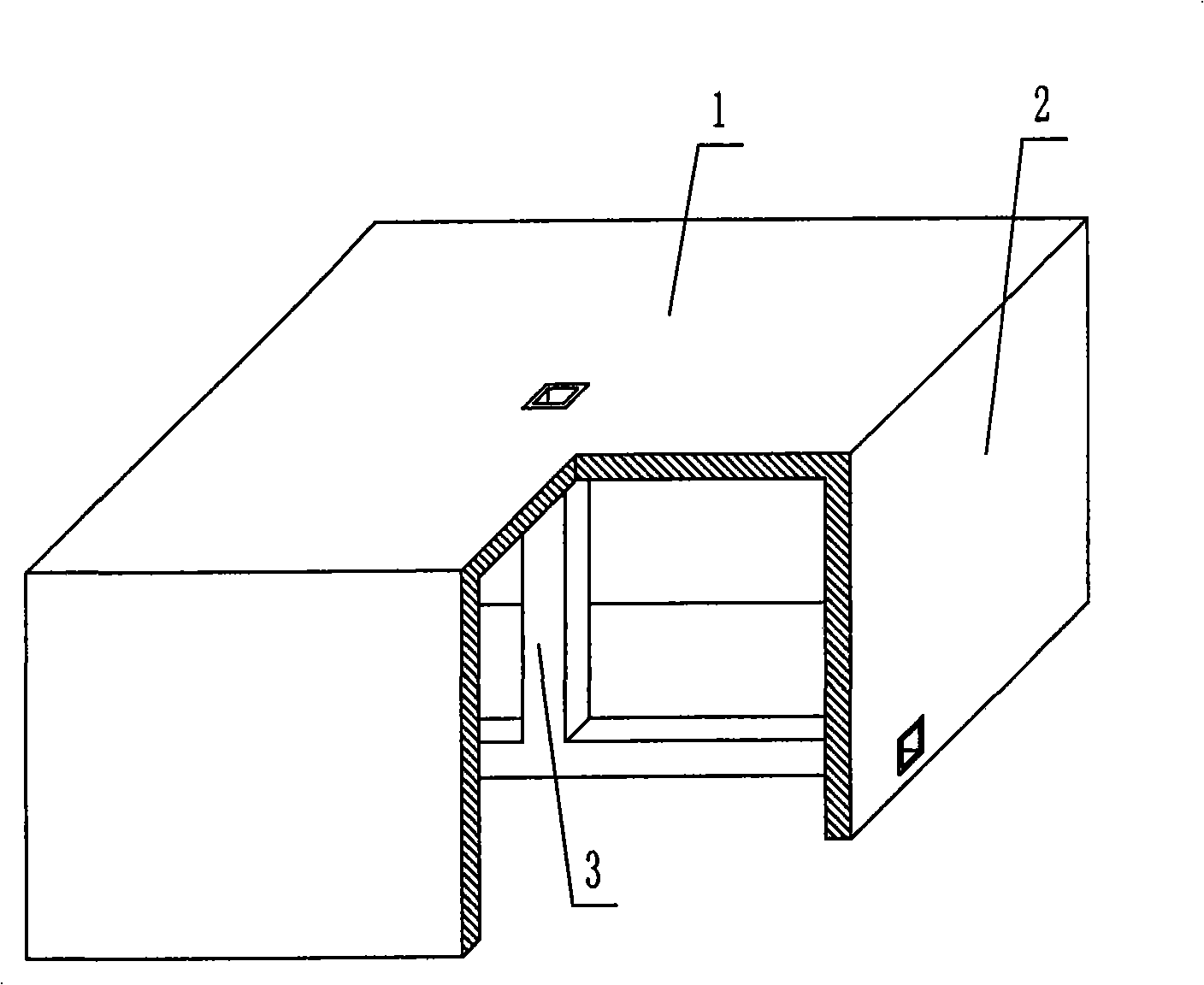
[0051] As shown in the accompanying drawings, the present invention includes an upper plate 1 and surrounding side walls 2, and the upper plate 1 and the surrounding side walls 2 form an open basin-shaped member, which is characterized in that the cavity of the basin-shaped member is provided with The stiffener 3 forms a whole with the pot-shaped member, and the surrounding side wall 2 protrudes outwards with a pick edge 4, and the pick edge 4 is formed by superimposing and cementing multiple layers of reinforcements 5 of tendons or nets glued with cementitious materials. figure 1 It is a structural schematic diagram of Embodiment 1 of the present invention. In each accompanying drawing, 1 is an upper plate, 2 is a surrounding side wall, and 3 is a stiffener. In the following accompanying drawings, those with the same number have the same description. ...


PUM


Abstract

A mould shell component comprises an upper board (1), a periphery lateral wall (2); an open basin-shaped component is enclosed by the upper board (1) and the periphery lateral wall (2), characterized in that the cavity of the basin-shaped component is arranged with a enforced rod (3) which integrates with the basin-shaped component; the periphery lateral wall (2) extents outwards as a stirring edge (4); the stirring edge (4) is adhered by the bar adhering a plurality layers of gel material and overlapped by the enforced objects (5). The mould shell component is suitable for the use of the hollow building, house cover, wall body basic bottom board and hollow bridge of the casting steel bar concrete or the pre-stress steel bar concrete, especially the use of the hollow beamless buildings.

Description

[0001] This application is a divisional application of the invention patent application with the filing date of December 15, 2003, the application number of 200310124190.X, and the title of "a formwork component". (1) Technical field [0002] The present invention relates to a formwork member. (2) Background technology [0003] At present, most of the buildings with brick-concrete structure and frame structure use prefabricated hollow-core slabs as floor slabs. This kind of floor slab has the advantages of fast construction speed and low cost, but because there is no firm connection between two adjacent prefabricated hollow-core slabs , Only cement mortar is used to fill the gaps, so not only the integrity is poor, which is not conducive to earthquake resistance, but also cracks and water seepage often occur, causing great inconvenience and psychological pressure to the residents. In order to solve the above problems, many buildings have adopted the method of cast-in-place c...

Claims


Application Information

Patent Timeline
IPC IPC(8): E04G11/36E04B5/36
Inventor 邱则有
Owner 湖南邱则有专利战略策划有限公司
Why Eureka
Try Eureka