
Vibrating failure diagnosis method based on determined learning theory

A technology for determining learning theory and fault diagnosis, applied in neural learning methods, vibration testing, testing of machine/structural components, etc. Achieve powerful approximation capabilities and improve the effect of automation

Inactive Publication Date: 2008-11-05
SOUTH CHINA UNIV OF TECH
View PDF0 Cites 32 Cited by
  • Summary
  • Abstract
  • Description
  • Claims
  • Application Information

AI Technical Summary

Problems solved by technology

[0008] Essentially, the fundamental problem with fault diagnosis is that it is difficult to model the system
If you avoid the modeling problem and only diagnose from symptoms and characteristic parameters, it is easy to cause misjudgment and missed judgment, and the reliability of the diagnosis result cannot be guaranteed.

Method used


Image

  • Vibrating failure diagnosis method based on determined learning theory
  • Vibrating failure diagnosis method based on determined learning theory
  • Vibrating failure diagnosis method based on determined learning theory

Examples


Embodiment

[0047] Consider the following system being diagnosed:

[0048] x · 1 = x 2 x · 2 = φ 2 s ( x 1 , x 2 ) , s = 0,1,2 - - - ( 1 ) ...


PUM


Abstract

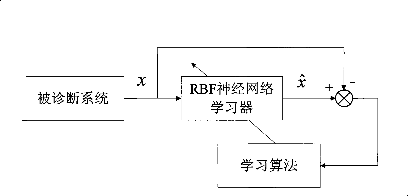
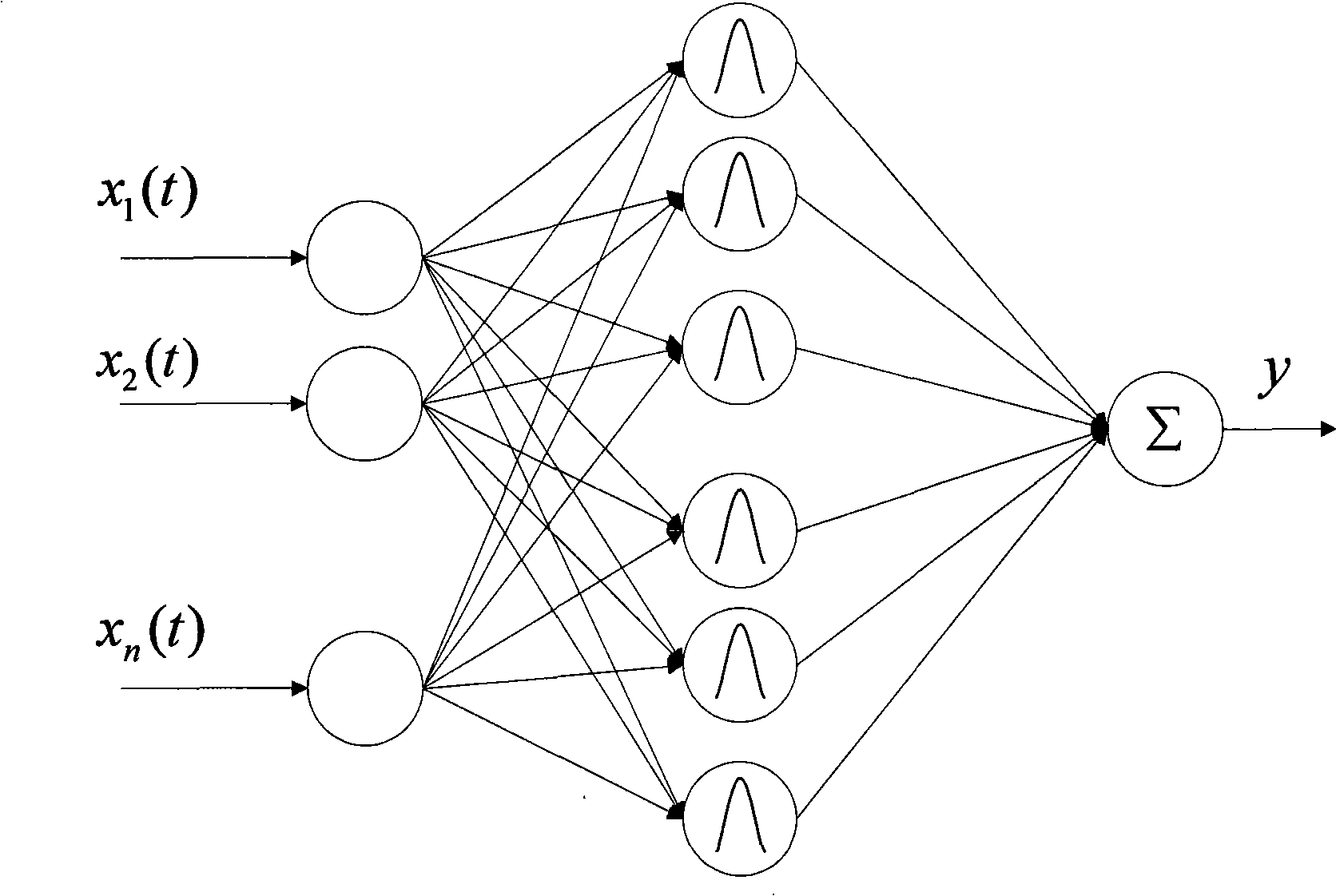
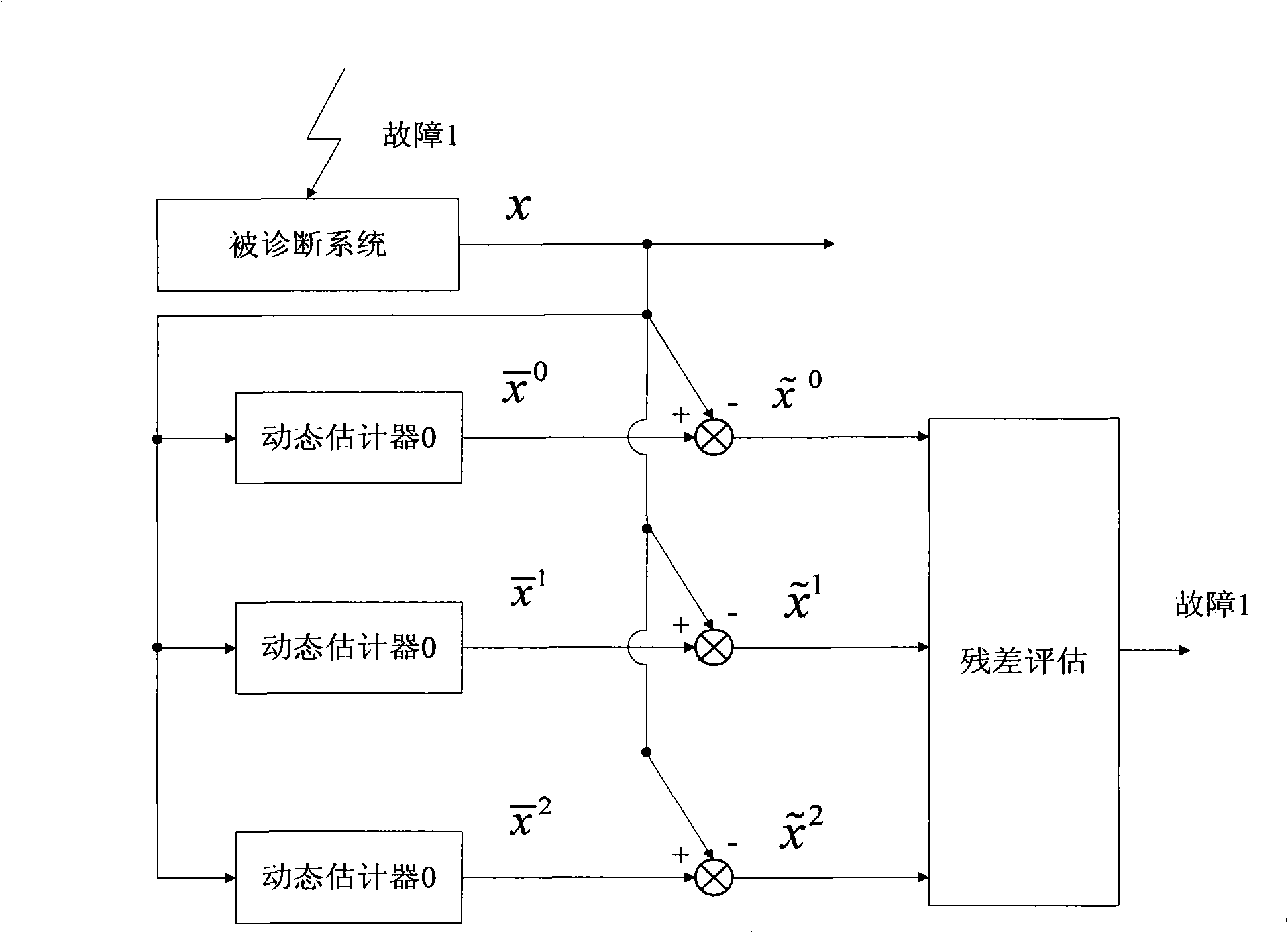
The present invention discloses a vibration fault diagnosis method based on confirming the learning theory. The method comprises the following steps: (1) executing learning exercise to the normal mode and fault mode of the diagnosed system; (2) establishing a mode database (comprising a normal mode and a fault mode); (3) establishing a dynamic estimator; (4) comparing the state of the dynamic estimator with the state of the detected system to generate a residual error; and (5) evaluating the residual error thereby discovering and eliminating the fault. The method is suitable for diagnosing the fault of complicated unknown non-linear vibration system. The unknown normal mode and fault mode can be studied to establish a mode database thereby executing fast failure discovery and elimination.

Description

technical field [0001] The invention belongs to the field of system fault diagnosis, and in particular relates to a vibration fault diagnosis method based on deterministic learning theory. Background technique [0002] Fault diagnosis is of great significance to modern engineering technology systems. Small faults will interrupt the production process and destroy products, while major faults will cause catastrophic consequences, such as personal injury and system paralysis. At present, the methods of fault diagnosis can be divided into methods based on analytical model, methods based on signal processing and methods based on knowledge (see Zhou Donghua, Ye Yinzhong, "Modern Fault Diagnosis and Fault-tolerant Control", Tsinghua University Press, 2000). The method based on the analytical model needs to establish the mathematical model of the monitored system, but in fact, the mathematical model of the system, especially the complex system, is difficult to obtain. The method b...

Claims


Application Information

Patent Timeline
IPC IPC(8): G01M7/02G06N3/08
Inventor 王聪陈填锐
Owner SOUTH CHINA UNIV OF TECH
Learn More