Method of producing seam-welded pipe having good welded portion characteristics

A resistance welding, characteristic technology, applied in manufacturing tools, high-frequency current welding equipment, welding equipment, etc., can solve problems such as production efficiency decline

Active Publication Date: 2008-11-05
JFE STEEL CORP
View PDF5 Cites 4 Cited by
  • Summary
  • Abstract
  • Description
  • Claims
  • Application Information

AI Technical Summary

Problems solved by technology

When using only the means for forming a taper on each strip edge, such as adjusting the cutting heads or planing rollers to the proper position so tha

Method used


Image

  • Method of producing seam-welded pipe having good welded portion characteristics
  • Method of producing seam-welded pipe having good welded portion characteristics
  • Method of producing seam-welded pipe having good welded portion characteristics

Examples


Embodiment 1

[0139] The following description will be made based on the examples.

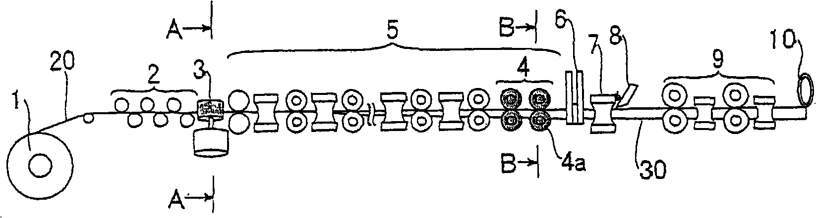
[0140] figure 1 The tube manufacturing machine used in the examples is shown. The pipe manufacturing method using this pipe manufacturing machine is as follows. The strip 20 is unrolled from the uncoiler 1; the strip is then re-flattened by a flattener 2; the strip 20 is then gradually rounded by a roll former 5; then the strip 20 is then rounded by means of a resistance welding machine (including an induction heating section 6 and squeeze roll (resistance welded part) 7) carry out electric resistance welding to the two transverse edges of the band that transversely becomes round, thereby form pipe 30; Then cut off the weld seam part of pipe 30 by weld seam cutter 8; The diameter machine 9 adjusts the outer diameter of the pipe 30 after cutting; and then the pipe is cut to a predetermined length by the pipe cutter 10 . The roll former 5 has a first roughing stand 13 at the previous stage, and a fin rolli...

Embodiment 2

[0146] In Inventive Example 2, except that the taper angle α in Inventive Example 1 was changed to 40°, the tube was manufactured in the same manner as in Inventive Example 1, and the tube was subjected to a Charpy test to evaluate its performance.

Embodiment 21

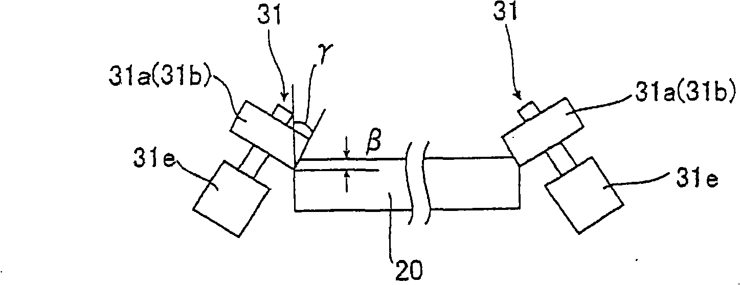
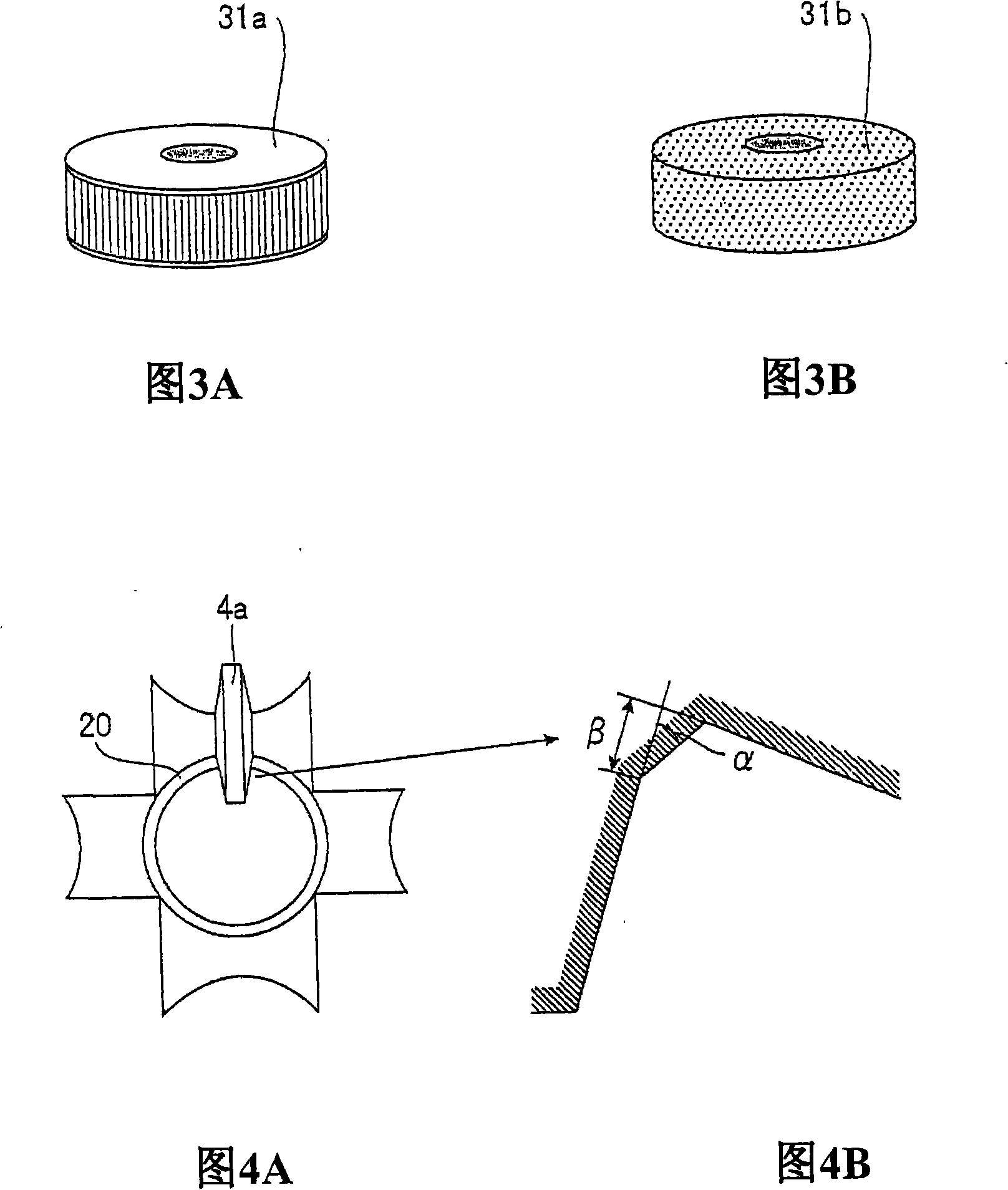
[0162] In Example 21 of the present invention, the above-mentioned electric resistance welded pipe was manufactured according to the first embodiment. In manufacture, a cutting roll 31a shown in FIG. 3A is employed as cutting or planing means 31 for forming tapers on both lateral edges at the upper surface side of the strip. The inclination angle α of the tapered shape was made to be 30° both at the upper surface side and the lower surface side. When the thickness of the strip is changed from 19.1mm to 11.3mm, the vertical position of the cutting roller 31a is moved down by 7.8mm for fine adjustment.


PUM

PropertyMeasurementUnit
Thicknessaaaaaaaaaa
Outer diameteraaaaaaaaaa
Thicknessaaaaaaaaaa

Abstract

The invention provides a method of efficiently manufacturing electric resistance welding pipes having excellent characterization of welded seams, by which each lateral edge of a rounded strip immediately before electric resistance welding is securely shaped with desired tapering flexibly in response to change in strip thickness, so that welding quality may be kept to be excellent. A method of manufacturing electric resistance welding pipes, in which a strip material (20) is subjected to forming, then edges thereof are formed to substantially face each other, and then the edges are subjected to electric resistance welding to form a pipe (30), wherein an edge and an edge opposed thereto at one of an upper-surface side and a lower-surface side of the strip are shaped with tapering before theforming by means of cutting or shaving (3), or fin-pass (4) forming.

Description

technical field [0001] The present invention relates to a method of manufacturing a pipe requiring weld toughness such as a line pipe for an oil well or a pipe requiring weld strength such as a casing for an oil well. Background technique [0002] In general, pipes can be broadly classified into welded pipes and seamless pipes. An electric resistance welded pipe, which is a type of welded pipe, is manufactured by bending a sheet into a circle by roll forming or the like, and then butting the edges and welding them. In welded pipe, the weld is generally less tough and strong than the parent strip. In the use of pipes, it is an inevitable problem to ensure a certain toughness and strength for each application. [0003] For example, because pipelines used to transport crude oil or natural gas are usually laid in cooler regions, toughness at low temperatures is a major consideration. Furthermore, strength is an important consideration for casing used to protect crude oil in o...

Claims


Application Information

Patent Timeline
IPC IPC(8): B23K13/00B21C37/083B23K101/06
Inventor 剑持一仁冈部能知横山泰康杉本祐二藤冈义文坂田敬井上智弘城泽广幸江木基明西田保夫村上宗义
Owner JFE STEEL CORP
Why Eureka
Try Eureka