Quiet propeller
A propeller, noiseless technology, applied in the direction of rotary propellers, machines/engines, non-variable pumps, etc., can solve problems such as rotational energy loss
- Summary
- Abstract
- Description
- Claims
- Application Information
AI Technical Summary
Problems solved by technology
Method used
Image

Examples
Embodiment approach 1
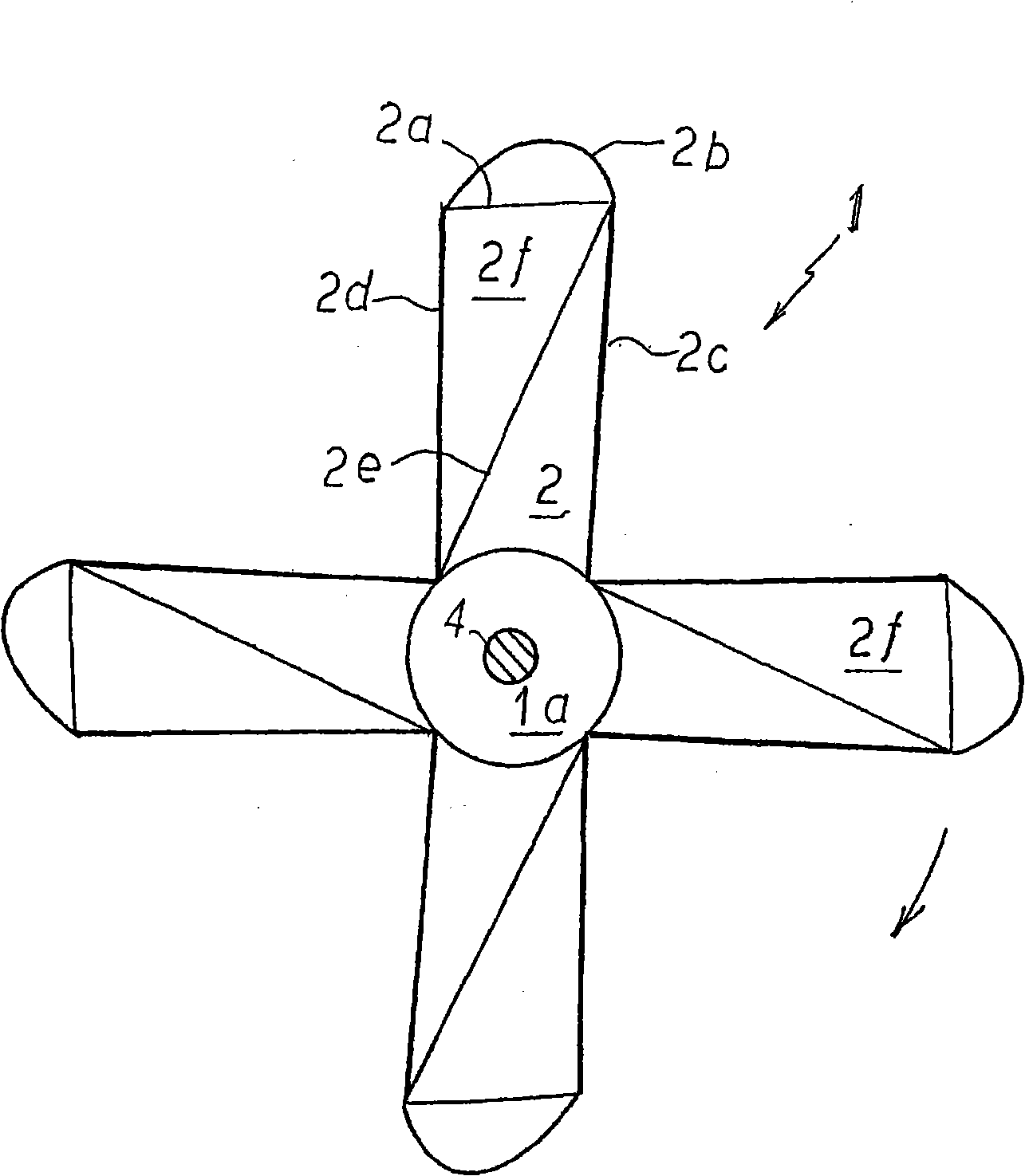
[0035] Embodiments of the present invention will be described below. figure 1 is the rear view of the noiseless thruster according to the present invention, figure 2 is the top plan view. The propeller 1 comprises four propeller blades 2 equally spaced around the punch 1a. The number of propeller blades 2 is not limited to four.
[0036] The base-to-tip lengths of the individual propeller blades 2 are substantially equal to each other. Between the first side 2c and the second side 2d is a bending line 2a.
[0037] From the bending line 2a, a tapered warped end portion 2b is formed.
[0038] The bent end portion 2b is bent from the bending line 2a.
[0039] Depending on the length of the blade 2b, the angle of the warped end 2b can vary between 15° and 45°.
[0040] exist figure 2 Among them, the warped tip 2b is 15% of the blade length, but can vary from 15% to 60%.
[0041] exist figure 1 In , the diagonal line 2e extends from the end of the first side 2c of the bl...
Embodiment approach 2
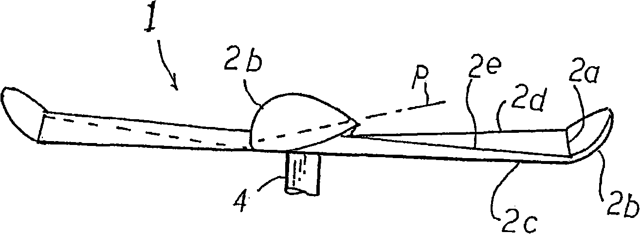
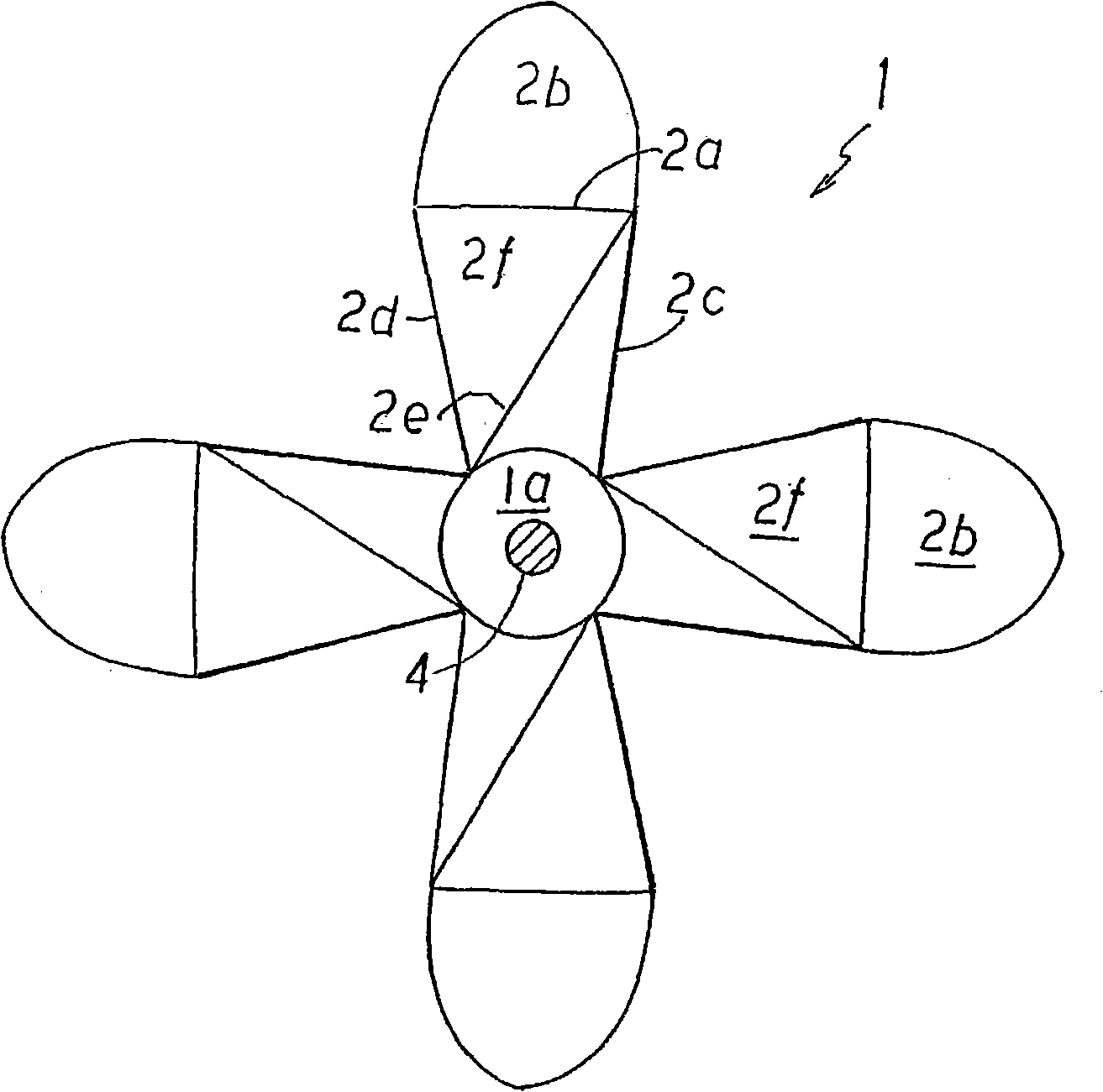
[0054] image 3 is a rear view of a second embodiment of a propeller according to the invention, Figure 4 is its top plan view.
[0055] In the second embodiment, the bending line 2 a of the propeller blade 2 is located at a distance of 40% of the propeller 1 radius from the peripheral end. The length of the warped end 2b is 40% of the length of the blade 2 or the radius of the propeller. But not limited to this.
[0056] The warped rear surface 2f and the warped end portion 2b having the pitch angle P are wider than those of the first embodiment so that the pushing amount of water can be increased. The length of the warped end portion 2 b is set to be 15% to 60% of the length of the blade 2 . If the warped end 2b is longer, the warped angle of the warped end 2b can be smaller.
Embodiment approach 3
[0058] Figure 5 is a rear view of a third embodiment of the thruster, Figure 6 is the top plan view. The description of the same components as those of the previous embodiment denoted by the same reference numerals will be omitted.
[0059] exist Figure 5 In the third embodiment, the distal end of the second side 2d of the propeller blade 2 contacts the bending line 2a. A diagonal line 2e extends from the aforementioned contact point to the proximal end of the first side 2c.
[0060] exist Figure 6 Among them, the first side 2c gradually becomes thinner from the punch 1a to the periphery of the pusher 1 . The propeller blades 2 are warped forward to form a pitch angle P with respect to the diagonal 2e. exist Figure 6 , the pitch angle P is in the range of 7 degrees to 25 degrees.
[0061]In the third embodiment, the pitch angle is not formed close to the center of the propeller 1 . Therefore, in high speed rotation, there is neither cavitation nor eddy current. ...
PUM
 Abstract
Description
Claims
Application Information