Water ejector of aircraft carrier

A technology for aircraft carriers and catapults, which is applied in the direction of launch/tow gears, etc., can solve the problems of steam energy utilization rate of only 6%, high cost of steam catapults, low efficiency of steam catapults, etc., so as to achieve the utilization rate of steam energy. High, low cost, the effect of increasing the contact area of ​​soda and water

Inactive Publication Date: 2008-11-12
尚德敏
View PDF0 Cites 17 Cited by
  • Summary
  • Abstract
  • Description
  • Claims
  • Application Information

AI Technical Summary

Problems solved by technology

[0030] (1) High maintenance cost, frequent and troublesome seal replacement, known as "Nightmare of the Navy";
[0031] (2) The cost of the steam catapult is high, there are many supporting facilities, and the system is cumbersome, with a volume of 1,000 cubic meters and a weight of 500 tons;
[00

Method used


Image

  • Water ejector of aircraft carrier
  • Water ejector of aircraft carrier
  • Water ejector of aircraft carrier

Examples


Embodiment Construction

[0081] The present invention will be described in further detail below in conjunction with the accompanying drawings and embodiments.

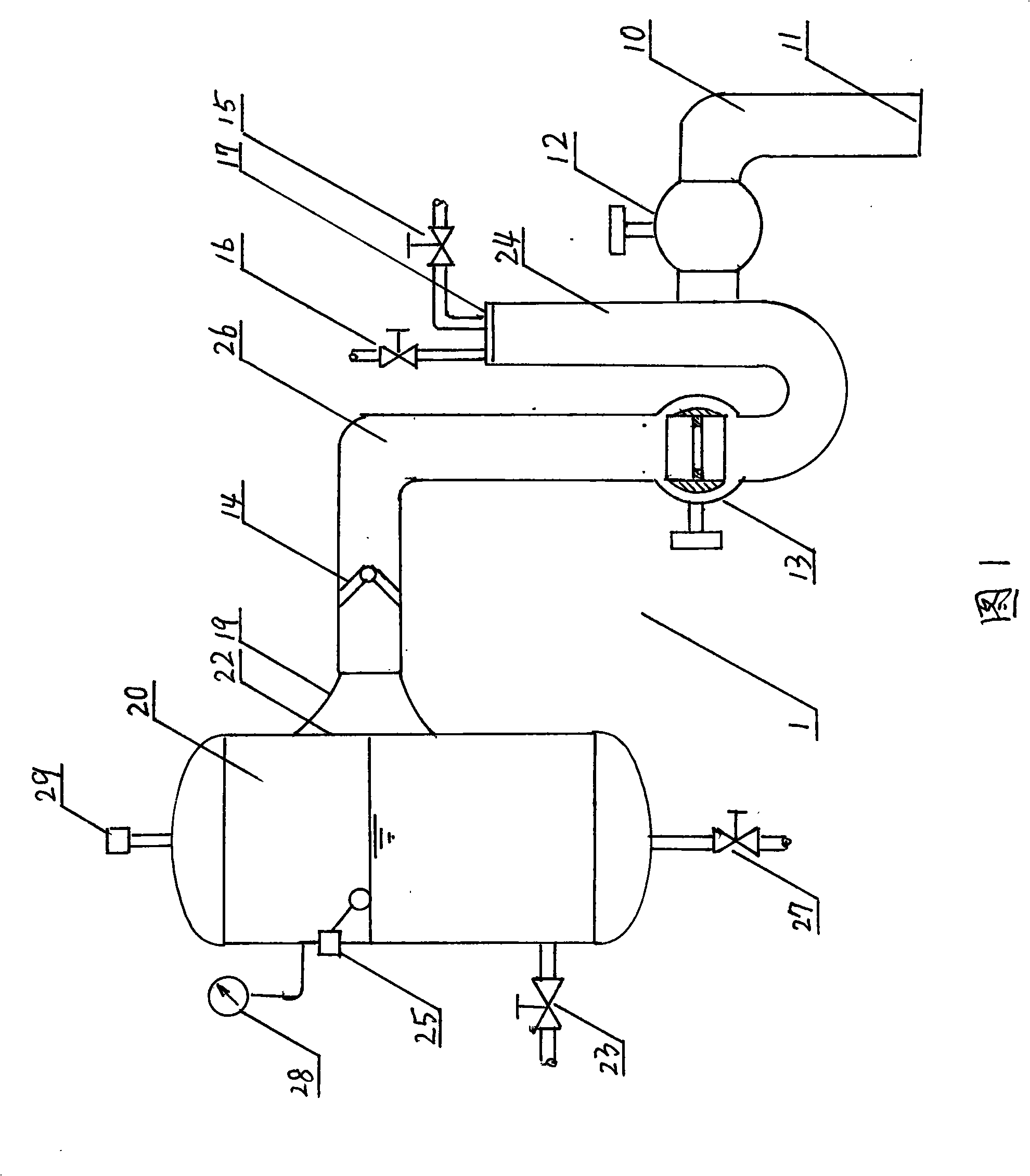
[0082] Fig. 1 is the structural diagram of the steam water feeder of the embodiment of the aircraft carrier hydraulic catapult of the present invention, the steam water feeder is made up of water inlet pipe, steam water pipe, booster pipe and pressure stabilizing tank, wherein, water inlet pipe, steam water pipe, booster pipe are combined again called a transducer.

[0083] The water inlet pipe 10 of the steam water feeder 1 is a right-angle elbow, and its inlet is vertically downwards, which is a water inlet 11. Before the water outlet, a water inlet valve 12 is set.

[0084] The steam water pipe 24 of the steam water feeder 1 is a J-shaped elbow, and the upper end of its vertical section is an inlet, which is closed by an end plate 17 on which an air valve 16 and a steam valve 15 are arranged. The air valve 16 is connected to the air source...


PUM

PropertyMeasurementUnit
Volumeaaaaaaaaaa

Abstract

The invention discloses an aircraft-carrier hydraulic ejector used for boosting the taking-off of aircrafts carried by the aircraft-carrier. The aircraft-carrier hydraulic ejector comprises a steam water-supply device, a water-supply controller, a circulation water tank, a water turbine, a water-turbine controller, a windlass, a reciprocating vehicle, a reversing vehicle, a stress bolt, a terminal sensor, a steam supply, an air supply and a fresh-water supply. The invention adopts steam to spray water to drive the water turbine, and then the water turbine drives the windlass, and the windlass drives the reciprocating vehicle, and then the reciprocating vehicle drives the carried aircraft to run and finally the carried aircraft is ejected. The steam water-supply which converts the heat energy of steam into the pressure potential energy of water and then does work through the water turbine is the core part of the invention, and comprises a steam-water pipe, a water intake, a pressure-rising pipe, a surge tank and a plurality of valves. The aircraft-carrier hydraulic ejector has the advantages that the energy converting mechanism is simple; the working is stable; the operation is convenient; the manufacturing cost is low; the maintenance work is less; the energy availability of steam is higher; the steam and water can be recycled; the heat loss is low and the manufacturing difficulty is low.

Description

technical field [0001] The invention relates to a catapult device on an aircraft carrier for boosting the take-off of a carrier-based aircraft, in particular to a hydraulic catapult for an aircraft carrier. Background technique [0002] The development of the catapult was developed with the advent of the aircraft carrier. According to data, when the commonly used jet carrier-based aircraft takes off, it needs to reach a speed of more than 330 kilometers per hour to stand up from the ground. Calculated based on the weight and engine power of the current aircraft, if there is no booster, the aircraft needs to roll several kilometers on the runway to reach the distance. Even the largest "Nimitz" class aircraft carrier today has a deck of only more than 300 meters, so , Relying on the catapult to accelerate the take-off speed is an essential link. [0003] The world's first catapult was successfully developed in 1911 by Captain Theodore Ellison of the United States. This prim...

Claims


Application Information

Patent Timeline
IPC IPC(8): B64F1/06
Inventor 尚德敏
Owner 尚德敏
Why Eureka
Try Eureka