Bundle target coupling sensor
A sensor-target coupling technology, applied in the field of photoelectric sensors, can solve the problems of inability to guarantee the accuracy and reliability of target shooting, difficult design and assembly of monitoring systems, deformation and scattering, etc., so as to shorten the laser guidance time, realize visualization, and improve adaptability Effect
- Summary
- Abstract
- Description
- Claims
- Application Information
AI Technical Summary
Problems solved by technology
Method used
Image
Examples
specific Embodiment approach 1
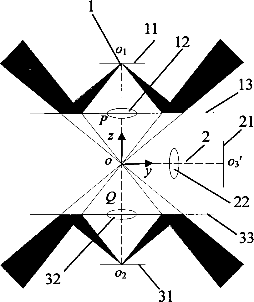
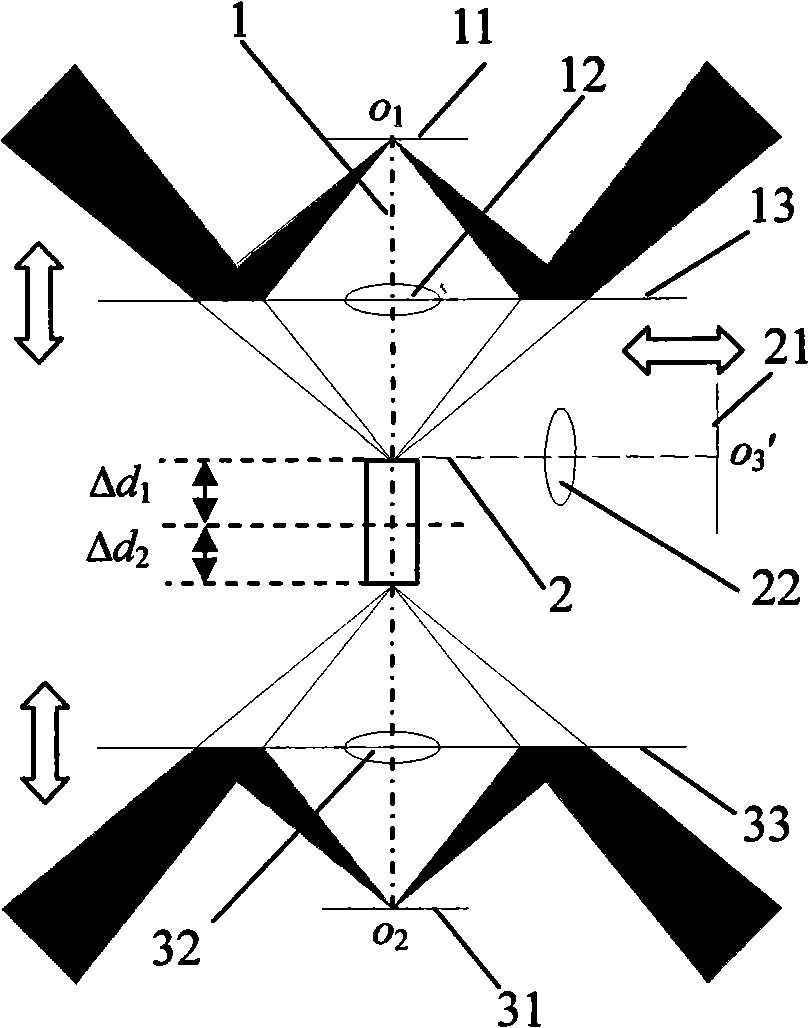
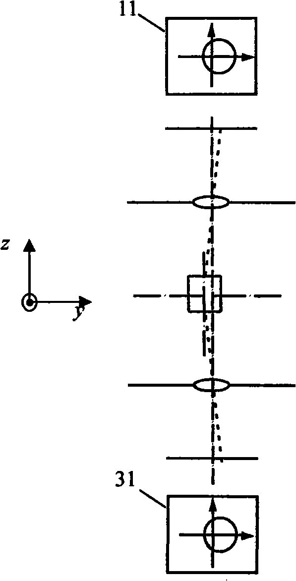
[0018] Specific implementation mode one: combine figure 1 , figure 2 and Figure 6 to Figure 1 0 illustrates this embodiment. The beam-target coupling sensor in this embodiment is composed of an upper monitoring unit, a middle monitoring unit, a lower monitoring unit, and a focusing mechanism;
[0019] The upper monitoring unit is composed of an upper CCD11, an upper microscope objective lens 12, an upper laser reflector 13 and an upper annular LED light source 14;
[0020] There is a circular hole in the middle of the upper laser reflector 13, and the upper microscopic objective lens 12 is fixed on the central position of the circular hole, and the optical axis of the upper microscopic objective lens 12 is perpendicular to the reflection surface of the upper laser reflective mirror 13 , the top of the upper microscopic objective lens 12 is provided with an upper road CCD11, and the upper annular LED light source 14 is installed on the bottom of the upper laser reflector 13...
specific Embodiment approach 2
[0028] Specific implementation mode two: combination Figure 6 to Figure 1 0 illustrates this embodiment, the difference between this embodiment and the specific embodiment is that the upper support frame 41, the lower support frame 42 and the middle monitoring unit support 44 are added; the upper support frame 41, the lower support frame 42 and the middle monitoring unit support 44 They are respectively used to fix the upper monitoring unit, the lower monitoring unit and the middle monitoring unit. Other compositions and connection methods are the same as those in Embodiment 1.
specific Embodiment approach 3
[0029] Specific implementation mode three: combination Figure 6 to Figure 1 0 illustrates this embodiment. The difference between this embodiment and Embodiment 2 is that the focus adjustment mechanism is composed of an upper focus adjustment mechanism, a lower focus adjustment mechanism, a middle focus adjustment mechanism 53 and a focus adjustment mechanism support frame 43; the upper focus adjustment mechanism consists of The upper transmission mechanism 511, the upper focus adjustment vacuum motor 512 and the upper rotation gear 513 are composed; the upper focus adjustment mechanism is used to vertically adjust the position of the upper support frame 41, and the lower focus adjustment mechanism consists of the lower transmission mechanism 521, the lower focus adjustment vacuum motor 522 It is composed of the lower rotating gear 523; the lower focusing mechanism is used to vertically adjust the position of the lower support frame 42, and the upper focusing vacuum motor 512 ...
PUM
 Abstract
Description
Claims
Application Information
 - R&D
- Intellectual Property
- Life Sciences
- Materials
- Tech Scout
- Unparalleled Data Quality
- Higher Quality Content
- 60% Fewer Hallucinations
Browse by: Latest US Patents, China's latest patents, Technical Efficacy Thesaurus, Application Domain, Technology Topic, Popular Technical Reports.
© 2025 PatSnap. All rights reserved.Legal|Privacy policy|Modern Slavery Act Transparency Statement|Sitemap|About US| Contact US: help@patsnap.com


