Explosion-proof battery

A battery and battery cartridge technology, applied to battery pack parts, circuits, electrical components, etc., can solve the problems of not being able to install explosion-proof devices, achieve the effects of reducing the difficulty of sealing, solving the limitation of strength, and simplifying the structure

Active Publication Date: 2012-05-23
湖北盐光能源科技有限公司
View PDF2 Cites 0 Cited by
  • Summary
  • Abstract
  • Description
  • Claims
  • Application Information

AI Technical Summary

Problems solved by technology

[0007] In order to overcome the above-mentioned defects, the purpose of the present invention is to overcome the above-mentioned technical defect that the explosion-proof device cannot be installed on the cover assembly with low mechanical strength of the battery container in the above-mentioned prior art, and to provide a battery container with high mechanical strength, such as using a steel shell battery Containers, or battery containers with low mechanical strength, such as battery containers made of aluminum, aluminum alloy, etc., are suitable for explosion-proof batteries

Method used


Image

  • Explosion-proof battery
  • Explosion-proof battery
  • Explosion-proof battery

Examples


Embodiment 1

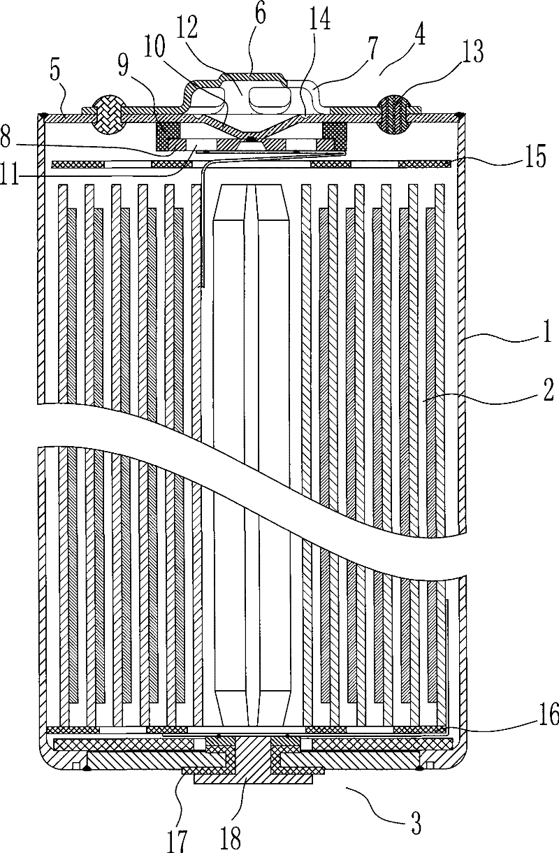
[0026] figure 1 The specific structure of an explosion-proof battery is shown, including: a battery cylinder 1, a battery unit 2 accommodated in the battery cylinder 1, a first cover assembly 3 and a second cover for leading out electrodes and sealing the battery cylinder 1 Component 4; the pole 18 of the first cover component 3 communicates with the negative pole of the battery unit 2, and is insulated from the battery cylinder 1 through an insulating gasket 17; the second cover component 4 that communicates with the positive pole of the battery unit 2 includes a substrate 5. A protective cover 6 with an air hole 7, a lead cover 8 and an insulator 9. The substrate 5 is directly welded to the battery cylinder 1 to seal it. The center of the substrate 5 forms a thin-walled explosion-proof membrane 10; the explosion-proof membrane 10 is umbrella-shaped It protrudes toward the inside of the battery, and the protruding part touches the center of the lead cover 8 and is electricall...

Embodiment 2

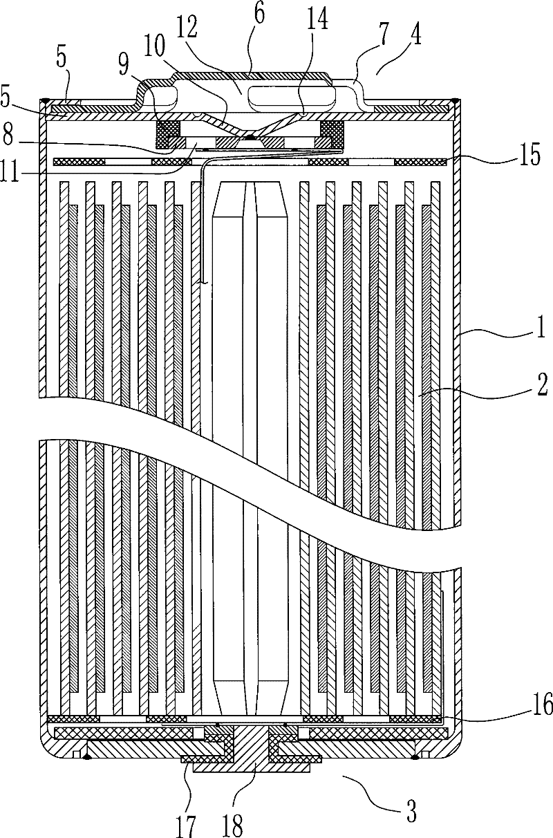
[0028] figure 2 The specific structure of another explosion-proof battery is shown, including the battery cylinder 1, the battery unit 2 accommodated in the battery cylinder 1, the first cover assembly 3 and the second cover assembly used to lead out the electrodes and seal the cylinder 1 4. The pole 18 of the first cover assembly 3 communicates with the negative pole of the battery unit 2 and is insulated from the battery cylinder 1 through the insulating gasket 17; the second cover assembly 4 communicated with the positive pole of the battery unit 2 includes a substrate 5 , a protective cover 6 with an air hole 7, a lead cover 8 and an insulator 9, the substrate 5 is directly welded to the battery cylinder 1 to seal it, wherein a thin-walled explosion-proof membrane 10 is formed at the center of the substrate 5; the explosion-proof membrane 10 is umbrella-shaped to The interior of the battery is raised, and the raised part is against the center of the lead cover 8, and is e...


PUM


Abstract

The invention discloses an explosion-proof battery, comprising a battery barrel, a battery unit housed in the battery barrel, a first cap component and a second cap component; the first cap component and the second cap component are used for sealing the battery barrel; the first cap component is electrically connected with the cathode of the battery unit; the second cap component electrically connected with the anode of the battery unit comprises a substrate which is hermetically connected with one end of the battery barrel, an explosion-proof device arranged on the substrate and a protectivecover correspondingly arranged outside the explosion-proof device; wherein, an insulation layer is arranged between the first cap component and the battery barrel; the second cap component is directly connected with the battery barrel; the protective cover is fixed by the substrate. Since the insulation layer is arranged between the first cap component and the battery barrel, the second cap component is directly connected with the battery barrel and no insulation layer is required to be arranged between the second cap component and the battery barrel, and the second cap component and the battery barrel can be sealed without using any flanging, thus eliminating the restriction of the battery to the strength of a battery vessel, reducing the sole weight of the battery and sealing difficulties.

Description

technical field [0001] The invention relates to a battery, more specifically, to an explosion-proof battery capable of bursting and releasing pressure when the temperature rises or the internal pressure of the battery rises. Background technique [0002] With the rapid development of audio, video camera equipment, personal computers and other electronic equipment in the direction of portability and mobility, high-capacity non-hydrolyzed secondary batteries represented by various alkaline batteries and lithium-ion batteries have become the The first choice for device drive power. [0003] Because this kind of high-capacity battery is sealed in a closed container, when the charger is overcharged or misused, abnormal gas will often be generated inside the battery. The accumulation of abnormal gas will cause excessive pressure inside the battery, resulting in The rupture of the battery presents a danger such as injury to electronic equipment or persons. In order to prevent the...

Claims


Application Information

Patent Timeline
Patent Type & Authority Patents(China)
IPC IPC(8): H01M2/02H01M2/12H01M2/14H01M2/34H01M50/143H01M50/166H01M50/184H01M50/186H01M50/342H01M50/578
CPCY02E60/10
Inventor 毛焕宇刘付勇赵俊峰
Owner 湖北盐光能源科技有限公司
Why Eureka
Try Eureka