
Sheet metal rigid particles or compressible powder half-module shaping technique

A technology of sheet metal and forming process, applied in metal processing equipment, forming tools, manufacturing tools, etc., can solve the problems of increasing production cycle and labor intensity, unfavorable automatic industrial production, reducing mold processing cost, etc., to improve the forming limit , The effect of realizing automatic production and improving production efficiency

Inactive Publication Date: 2008-11-19
YANSHAN UNIV
View PDF0 Cites 20 Cited by
  • Summary
  • Abstract
  • Description
  • Claims
  • Application Information

AI Technical Summary

Problems solved by technology

But this process has the following problems: After the rigid particles replace the punch to form the sheet, it needs to be demoulded together with the sheet and the particles at the same time, and then proceed to the next process of forming, placing the sheet and adding particles, thus greatly improving the production cycle. At the same time, it is not conducive to the automatic industrial production of this process; at the same time, because the concave mold is more difficult to process than the convex mold, the concave mold of parts with complex shapes still needs to be processed, so the reduction of mold processing costs is also limited

Method used


Image

  • Sheet metal rigid particles or compressible powder half-module shaping technique
  • Sheet metal rigid particles or compressible powder half-module shaping technique
  • Sheet metal rigid particles or compressible powder half-module shaping technique

Examples


Embodiment 1

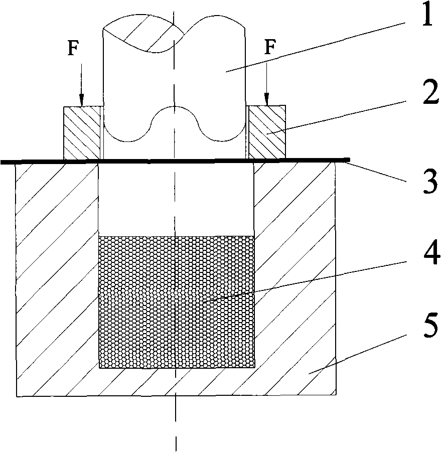
[0020] a. Design a cylindrical mold punch 1 with a diameter of Φ50mm and a height of 100mm; design a box 4 with an inner diameter of Φ62mm, an outer diameter of Φ200mm, and a height of 100mm for rigid solid particles; the inner diameter of the blank holder 2 is Φ52mm, outer diameter Φ150mm, thickness 30mm.

[0021] b. Add rigid solid particles 5 (steel balls) with a diameter of 2mm into the box body 4, and the loading height is 40mm.

[0022] c. Put the 08 steel plate with a diameter of Φ200mm and a thickness of 0.8mm on the box 4 filled with rigid solid particles 5 (steel balls), and load the blankholder 2 with a blankholder force of 2MPa.

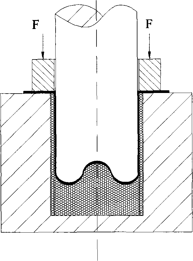
[0023] d. Load 5000-10000N on the mold punch 1, and when the rigid solid particles 5 fill the entire cavity of the concave mold, the drawing of the cylindrical part is completed.

[0024] e. After the mold punch 1 returns, the part is ejected, and the rigid solid particles 5 are automatically reset to form the next part.

Embodiment 2

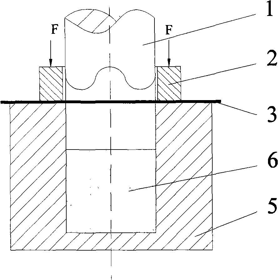
[0026] a. Design a cylindrical mold punch 1 with a diameter of Φ50mm and a height of 100mm; design a box 4 with an inner diameter of Φ62mm, an outer diameter of Φ200mm, and a height of 100mm filled with compressible powder 6; the inner diameter of the blank holder 2 It is Φ52mm, the outer diameter is Φ150mm, and the thickness is 30mm.

[0027] b. Add compressible powder 6 into the box body 4, pre-press the compressible powder 6 with a pressure of 15MPa, and fill it at a height of 40mm.

[0028] c. Put the 08 steel plate 3 with a diameter of Φ200mm and a thickness of 0.8mm on the box 4 filled with compressible powder 6, and load the blankholder 2 with a blankholder force of 2MPa.

[0029] d. Load 5000-10000N to the mold punch 1, when the compressible powder 6 fills the entire cavity of the concave mold, the drawing of the cylindrical part is completed.

[0030] e. Eject the part, add a certain amount of compressible powder 6 again to form the next part, or use a stirring or vi...


PUM

PropertyMeasurementUnit
heightaaaaaaaaaa
thicknessaaaaaaaaaa
thicknessaaaaaaaaaa

Abstract

The invention discloses a flexible die forming technique of sheet metal rigid particles or compressible powder, which is characterized in that: a. a male die (1) of a die is designed, processed and manufactured based on the shape and the size of forming sheet metal parts; b. a case body (4) is designed, and the rigid particles or the compressible powder is placed in the case body (4); c. the sheet metal (3) is placed on the case body (4), and is held down by a blank holder (2); d. under the action of a pressure P, the male die (1) of the die moves downwards, the female die shape is formed by the movement of the solid rigid particles (4), or is formed by compressing the compressible powder (6), thus forming the sheet metal; e. the male die (1) of the die returns, the parts are ejected or directed taken down from the case body (4), and the forming of the next part goes on; and f. if the case body (4) is filled with the solid rigid particles (4), the particles automatically reset after the die (1) of the die returns; and if the case body (4) is filled with the compressible powder (6), the forming of the next part goes on after adding a certain amount of power again, or after dispersing the powder by adopting a stirring device or a vibrating device. The technique of the invention can increase the forming limit of the sheet metal, facilitate the machining forming of the parts with complex shapes, reduce the processing cost of the die, improve the labor efficiency and facilitate the realization of automation.

Description

technical field [0001] The invention relates to the technical field of metal precision forming, in particular to a metal plate rigid particle or compressible powder half-mold forming process Background technique [0002] Sheet metal forming plays an important role in industries such as automobile, aviation, aerospace and electronics, and the requirements for dimensional accuracy, surface quality, shape complexity and forming limit of sheet metal formed parts are getting higher and higher. Research on a new process that can overcome the shortcomings of conventional processes, has simple mold making, short cycle time, low cost, and can improve the performance of sheet metal forming has become the main research direction of sheet metal forming research. [0003] Sheet metal soft mold forming technology provides an effective way to solve these technical problems. In the half-mold forming process of sheet metal, the cold half-mold forming includes hydroforming with water (emulsi...

Claims


Application Information

Patent Timeline
Patent Type & Authority Applications(China)
IPC IPC(8): B21D22/02B21D37/10
Inventor 骆俊廷顾勇飞
Owner YANSHAN UNIV
Learn More