Side light type luminous diode backlight

A light-emitting diode and side-light technology, which is applied in the field of improved structure of side-light light-emitting diode backlight heat dissipation, can solve the problems of power increase and dissipation of light-emitting diode lamp groups, and achieve the effect of avoiding light leakage and improving heat dissipation performance

Active Publication Date: 2008-11-19
BOE TECH GRP CO LTD
View PDF0 Cites 28 Cited by
  • Summary
  • Abstract
  • Description
  • Claims
  • Application Information

AI Technical Summary

Problems solved by technology

[0006] The defect of the prior art is that the LED lamp group in the side-lit LED backlight is in a completely closed environment, therefore, the heat dissipation path generated by the LED lamp group after lighting is mainly through the heat conduction of the circuit board. to the backplane, and then dissipated into the air. As the brightness of the LED lamp group and the size of the backlight increase, the power of the LED lamp group will gradually increase, and the problem of heat dissipation will become more prominent.

Method used


Image

  • Side light type luminous diode backlight
  • Side light type luminous diode backlight
  • Side light type luminous diode backlight

Examples


Embodiment 1

[0025] figure 2 Shown is a schematic cross-sectional view of Embodiment 1 of the side-light LED backlight source of the present invention, as figure 2 As shown, the side-light LED backlight source includes a LED lamp group 21, a circuit board 22, a back plate 23, a reflector 24, a light guide plate 25, an optical film group 26 and a frame 27; the LED lamp group 21 consists of a LED lamp The light-emitting diode is a top-emitting type, and the light-emitting diode lamp group 21 is directly welded on the circuit board 22, and the circuit board 22 is mounted on the inner side of the back plate 23; the light guide plate 25 is close to the upper surface of the lower side of the reflector 24; the optical film The group 26 covers the upper surface of the light guide plate 25, and the above-mentioned components are assembled together by the frame 27; the reflector 24 is L-shaped, and the top of the reflector 24 is connected with the optical film group 26, so that the reflective surf...

Embodiment 2

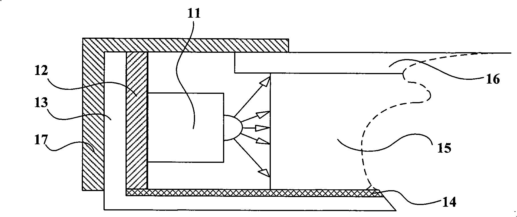
[0027] image 3 Shown is a schematic cross-sectional view of Embodiment 2 of the side-light LED backlight source of the present invention, as image 3 As shown, the side-light LED backlight includes LED lamp group 31, circuit board 32, back plate 33, reflector 34, light guide plate 35, optical film group 36 and frame 37; in this embodiment, the LED lamp group 31. The structural relationship between the frame 37, the back plate 33, the reflection plate 34, the light guide plate 35 and the optical film group 36 is the same as that in the first embodiment, the light guide plate 35 is close to the upper surface of the lower side of the reflection plate 34; the optical film group 36 covers the The upper surface of the light plate 35, therefore, the enclosed space is also the same as in Embodiment 1; the difference is that the LED lamp group 31 is made up of side-emitting LED lamps, therefore, the circuit board 32 for the power supply of the LED lamp group is mounted on The bottom ...

Embodiment 3

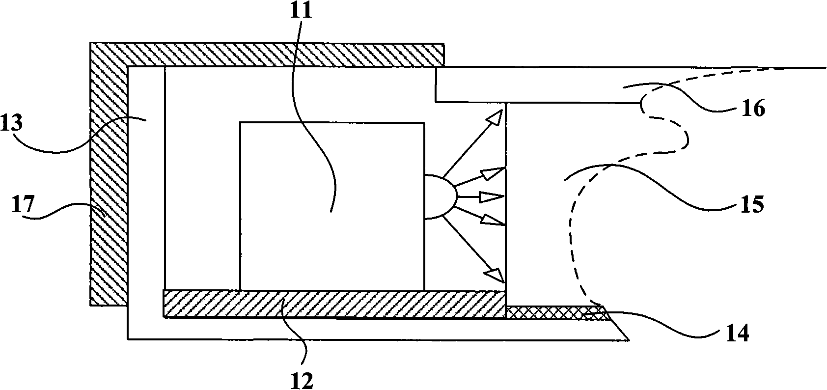
[0029] Figure 4 It is a schematic cross-sectional view of Embodiment 3 of the side-light LED backlight source of the present invention, as shown in Figure 4As shown, the side-light LED backlight includes a LED lamp group 41, a circuit board 42, a back plate 43, a reflector 44, a light guide plate 45, an optical film group 46 and a frame 47; in this embodiment, the LED lamp group 41. The structural relationship between the frame 47, the reflection plate 44, the light guide plate 45 and the optical film group 46 is the same as that in the first embodiment, the light guide plate 45 is close to the upper surface of the lower side of the reflection plate 44; the optical film group 46 covers the upper surface of the light guide plate 45 , Therefore, the enclosed space is also the same as in Embodiment 1; the difference is that the edge of the back plate 43 is n-shaped, the LED lamp group 41 is made up of top-emitting LED lamps, and the circuit board 42 for power supply of the LED ...


PUM


Abstract

The invention relates to an side light type LED backlight, which comprises a LED lamp set, a light guide plate, an optical film group, wherein the light leaving surface of the LED lamp set, the incident plane of the optical film group are in a closed space; the space, in which the LED lamp set except the light leaving surface is arranged, is communicated with the exterior space of the side light type LED backlight. In the proposal, the closed space of the side light type LED backlight can avoid light-leakage, and because the space, in which the LED lamp set except the light leaving surface is arranged, is communicated with the exterior space of the side light type LED backlight, energy emitted by a Led lamp set base can be quickly transmitted to the exterior space, thereby improving heat dissipation performance of the side light type LED backlight and avoiding light- leakage furthest.

Description

technical field [0001] The invention relates to a side-light backlight source, in particular to an improved heat dissipation structure of a side-light light-emitting diode backlight source. Background technique [0002] Currently, backlights are usually classified into direct-lit backlights and edge-lit backlights due to different positions of light sources. The direct-lit backlight has no light guide plate, and the light source is directly placed directly under the optical film group; the edge-lit backlight has a light guide plate, and the light source is placed on the side of the light guide plate, and the point light source or line light source is converted into a surface light source. [0003] In recent years, edge-lit backlights have attracted much attention because of their lightness and thinness, and the edge-lit backlights that use light-emitting diode lamps as light sources, that is, edge-lit LED backlights, have good color reproduction, convenient color management,...

Claims


Application Information

Patent Timeline
Patent Type & Authority Applications(China)
IPC IPC(8): F21V29/00F21V8/00F21V7/10G02F1/13357F21Y101/02F21Y105/00F21V29/50F21Y115/10G02F1/1335
Inventor 王庆江张丽蕾万丽芳孙小斌王刚邵喜斌
Owner BOE TECH GRP CO LTD
Why Eureka
Try Eureka