
Backlight module group and its optical plate

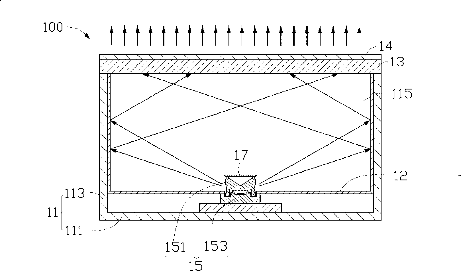
A backlight module and optical board technology, applied in optics, optical components, nonlinear optics, etc., can solve the problem of uneven light output from the backlight module 100

Inactive Publication Date: 2008-11-19
HONG FU JIN PRECISION IND (SHENZHEN) CO LTD +1
View PDF0 Cites 0 Cited by
  • Summary
  • Abstract
  • Description
  • Claims
  • Application Information

AI Technical Summary

Problems solved by technology

The matching design of the light-emitting diode 15 and the reflector 17 can reduce the bright area directly above the light-emitting diode 15 to a certain extent, but the backlight module 100 still has the disadvantage of uneven light output.

Method used


Image

  • Backlight module group and its optical plate
  • Backlight module group and its optical plate
  • Backlight module group and its optical plate

Examples


Embodiment Construction

[0019] The backlight module and its optical board of the present invention will be further described in detail below with reference to the drawings and embodiments.

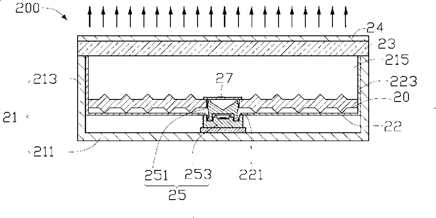
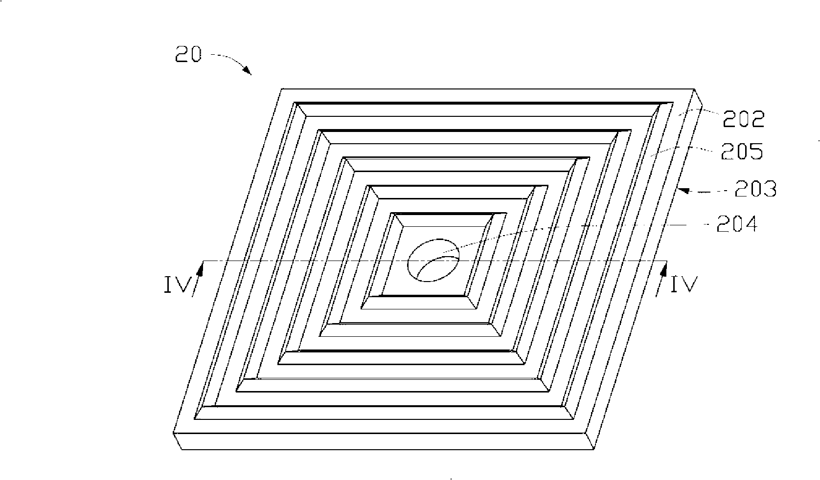
[0020] See figure 2 , shows the backlight module 200 of the preferred embodiment 1 of the present invention, which includes a frame 21 , a reflector 22 , a diffuser 23 , an edge-type point light source 25 and an optical plate 20 . The frame 21 includes a rectangular bottom plate 211 and four sidewalls 213 vertically extending from the edge of the bottom plate 211 to the same side thereof and connected to each other. The four side walls 213 together with the bottom plate 211 form a cavity 215 . The diffuser plate 23 is disposed on top of the plurality of sidewalls 213 for covering the cavity 215 . The cavity 215 can accommodate components such as the point light source 25 , the reflection plate 22 and the optical plate 20 . The light emitted from the point light source 25 can be emitted through the diffuser pl...


PUM

PropertyMeasurementUnit
angleaaaaaaaaaa

Abstract

Disclosed is an optical plate which comprises at least one optical plate unit, each optical plate unit includes a light exit surface and a bottom surface relative to the light exit surface. The light exit surface and the bottom surface are respectively provided with a plurality of closed type V-shaped bulges. The bottom surface is provided with at least one light source containing part. The invention also provides a backlight module group adopting the optical plate, and the backlight module group has the advantage of uniform light exit.

Description

technical field [0001] The invention relates to a backlight module and its optical board, in particular to a backlight module for liquid crystal display and its optical board. Background technique [0002] Since the liquid crystal itself of the liquid crystal display panel does not have light-emitting properties, it is necessary to provide a light source device, such as a backlight module, for the liquid crystal display panel in order to achieve a display effect. The function of the backlight module is to supply a surface light source with sufficient brightness and uniform distribution to the LCD panel. [0003] See figure 1 , shows a conventional backlight module 100 , which includes a frame 11 , a reflector 12 , a diffuser 13 , a prism sheet 14 and a light emitting diode 15 . The frame 11 includes a rectangular bottom plate 111 and four sidewalls 113 vertically extending from the edge of the bottom plate 111 to the same side thereof. The bottom plate 111 and the plurali...

Claims


Application Information

Patent Timeline
Patent Type & Authority Applications(China)
IPC IPC(8): G02B6/00G02F1/13357G02F1/1335
CPCG02B6/0028G02B6/0018G02B6/0021G02B6/0031G02B6/0038G02B6/0073
Inventor 章绍汉
Owner HONG FU JIN PRECISION IND (SHENZHEN) CO LTD
Learn More