Polycrystalline silicon single side removing method

A polysilicon, unilateral technology, used in electrical components, semiconductor/solid-state device manufacturing, circuits, etc., can solve the problems of the dielectric material 218 becoming larger and smaller, affecting the electrical performance of the device, etc., to reduce lateral etching, Improve the effect of easily damaged adjacent silicon structure and improve control force

Inactive Publication Date: 2008-11-26
SEMICON MFG INT (SHANGHAI) CORP
View PDF1 Cites 2 Cited by
  • Summary
  • Abstract
  • Description
  • Claims
  • Application Information

AI Technical Summary

Problems solved by technology

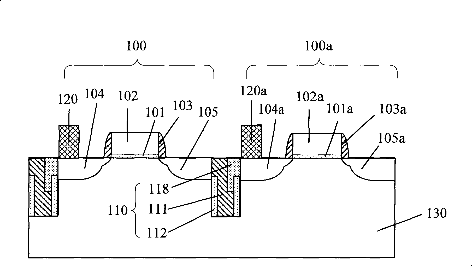
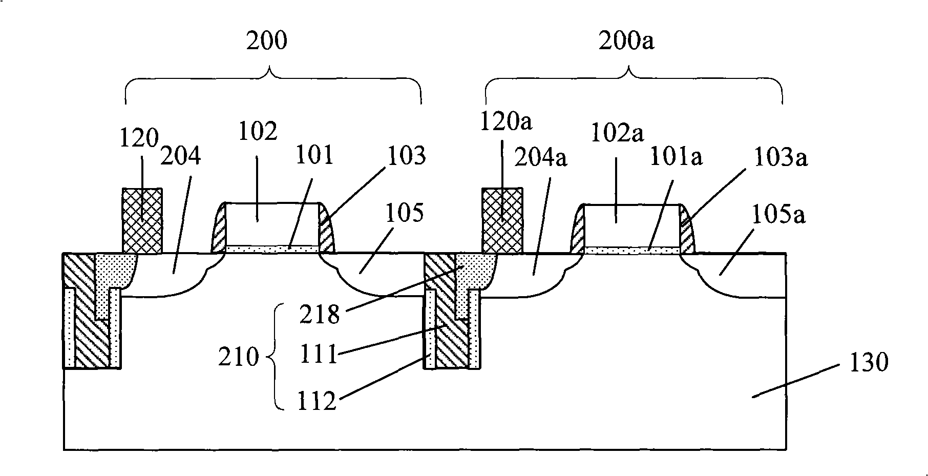
[0007] figure 2 It is a schematic cross-sectional view of the device when the existing polysilicon unilateral removal process is abnormal, such as figure 2 As shown, during the unilateral removal process of the polysilicon 111, the etching gas will react with the silicon material in the drain region 104a of the adjacent device at the same time, and a lateral etching phenomenon occurs, resulting in the drain region 204a of the MOS device adjacent to the polysilicon damaged, ( figure 2 The same problem also exists in the drain region 204 of the MOS device 200 in the MOS device), at this time, the size of the drain region 204a of the adjacent MOS device will become smaller, and the size of the dielectric material 218 filled in the trench 210 will become larger
In this way, when the bit line 120 is formed on the drain region 204a of the MOS device 200a in the subsequent process, the contact area between the bit line 120 and the highly doped drain region 204a is correspondingly reduced, while the contact area with the dielectric material 218 is correspondingly increased, As a result, the contact resistance of the bit line increases, which affects the electrical performance of the device

Method used


Image

  • Polycrystalline silicon single side removing method
  • Polycrystalline silicon single side removing method
  • Polycrystalline silicon single side removing method

Examples


Embodiment Construction

[0038] In order to make the above objects, features and advantages of the present invention more comprehensible, specific implementations of the present invention will be described in detail below in conjunction with the accompanying drawings.

[0039] The processing method of the present invention can be widely used in various fields, and can utilize many suitable materials to make, and below is to illustrate by preferred embodiment, certainly the present invention is not limited to this specific embodiment, this field Common replacements known to those skilled in the art undoubtedly fall within the protection scope of the present invention.

[0040] Secondly, the present invention is described in detail using schematic diagrams. When describing the embodiments of the present invention in detail, for the convenience of explanation, the cross-sectional view showing the device structure will not be partially enlarged according to the general scale, which should not be used as a ...


PUM


Abstract

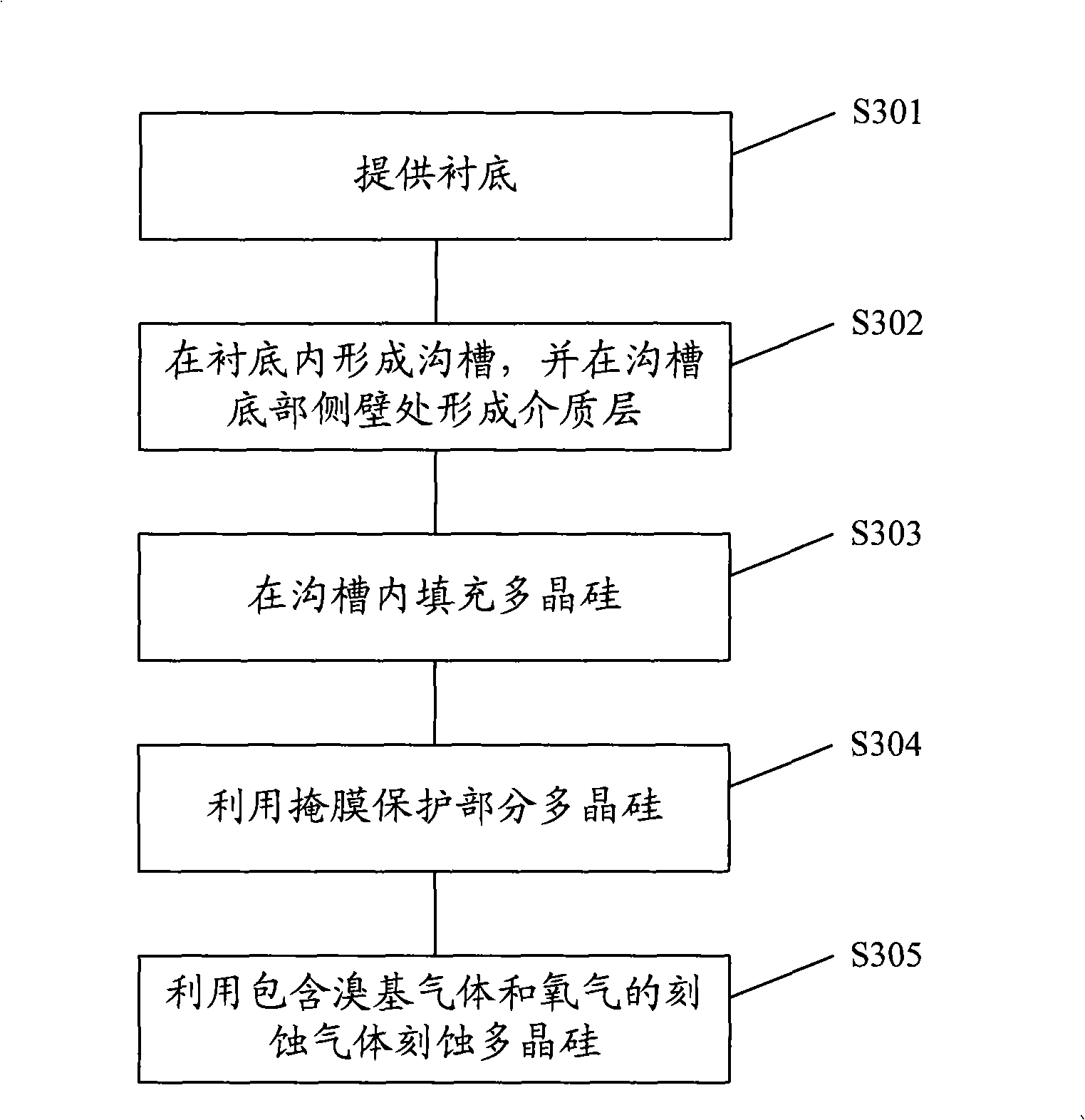
The invention discloses a polysilicon single edge removing method, which comprises steps of providing a substrate with a groove in which polysilicon filled, forming mask on parts of the area of the polysilicon surface, and etching the polysilicon by utilizing etching gas including bromo-gas and oxygen-containing gas. The polysilicon single edge removing method increases the control of etching to shape of sidewall, and reduces damage to adjacent silicon structure in the polysilicon single edge removing process.

Description

technical field [0001] The invention relates to the technical field of semiconductor manufacturing, in particular to a polysilicon unilateral removal method. Background technique [0002] The process of manufacturing semiconductor integrated circuit chips uses batch processing technology to form a large number of various types of complex devices on the same silicon substrate and connect them to each other to have complete electronic functions. With the rapid development of ultra-large-scale integrated circuits, the integration of chips is getting higher and higher, and the size of components is getting smaller and smaller. The various effects caused by the high density and small size of devices have an increasing impact on the results of semiconductor process manufacturing. protrude. [0003] Taking the manufacture of trench DRAM cells as an example, due to the proportional decrease in device size, higher requirements are imposed on the process of removing polysilicon (SSBT...

Claims


Application Information

Patent Timeline
IPC IPC(8): H01L21/308
Inventor 李宗亮卓起德
Owner SEMICON MFG INT (SHANGHAI) CORP
Why Eureka
Try Eureka