Slurry bed reactor and uses thereof

A slurry bed and reactor technology, which is applied to slurry bed reactors and their application fields, can solve the problems of complex equipment, low production efficiency, and heavy equipment, and achieves the advantages of reducing circulation circulation, uniform distribution, and improving filtration effect. Effect

Active Publication Date: 2008-12-03
CHINA PETROLEUM & CHEM CORP +1
View PDF7 Cites 42 Cited by
  • Summary
  • Abstract
  • Description
  • Claims
  • Application Information

AI Technical Summary

Problems solved by technology

However, using a single settling technology to achieve complete liquid-solid separation and obtaining a liquid product with a very small solid content requires a settling device with a large volume to ensure sufficient settling time, which results in most of the area and space of the equipment being covered by the settling device. In addition, the smaller the particle size of the catalyst, the more conducive the reaction is to proceed. At the same time, during the reaction process, due to the wear of the catalyst, a solid powder with a very small particle size will be produced, but the sedimentation technology is suitable for particle sizes of several microns or The separation effect of smaller catalyst particles is not good; due to the considerable diameter of the Fischer-Tropsch synthesis reactor, it is difficult for the magnetic field device to generate a uniform magnetic field in the reactor, and the equipment is heavy and expensive, and it is impossible to demagnetize the magnetized catalyst To prevent the agglomeration of the magnetized catalyst and affect the normal operation of the reactor
[0008] WO 94/16807 discloses a method of using a filter assembly in a reactor to achieve liquid-solid separation,...

Method used


Image

  • Slurry bed reactor and uses thereof
  • Slurry bed reactor and uses thereof
  • Slurry bed reactor and uses thereof

Examples


Embodiment 1

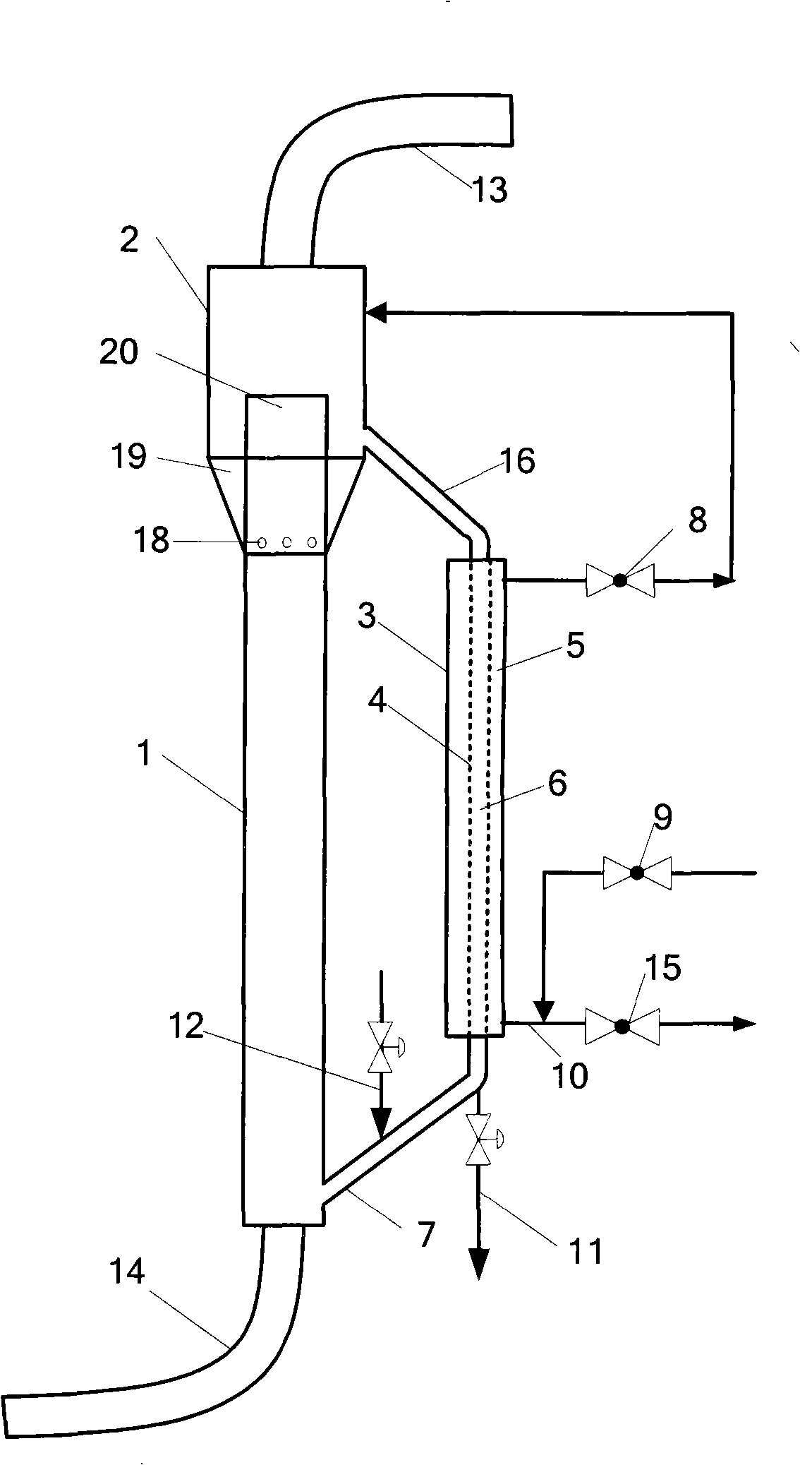
[0061] Use as attached figure 1 In the shown reactor, the flow disturbance zone 20 and the steady flow zone 19 are separated by a cylindrical baffle, and the bottom of the steady flow zone 19 communicates with the reaction zone through the opening at the bottom of the baffle. where the size of the reaction zone is 70×3200mm; the diameter of the expansion section of the settlement zone is 150mm, and the height is 1000mm; the size of the cylindrical baffle is 70×700mm, there are 6 openings at the bottom of the baffle 12 holes; the outer tube size of the downcomer is 70×2000mm, the inner filter tube is made of metal microporous membrane, and the size of the filter tube is 30×1800mm, average pore size 1.0μm.

[0062] The composition of the catalyst is: containing 20.3% by weight of Co 2 o 3 , 76.1 wt% SiO 2 , 3.6% by weight of MgO. The preparation method is to contain Co(NO 3 ) 3 and Mg(NO 3 ) 2 solution impregnated SiO 2 The microsphere carrier is left to stand ...

Embodiment 2

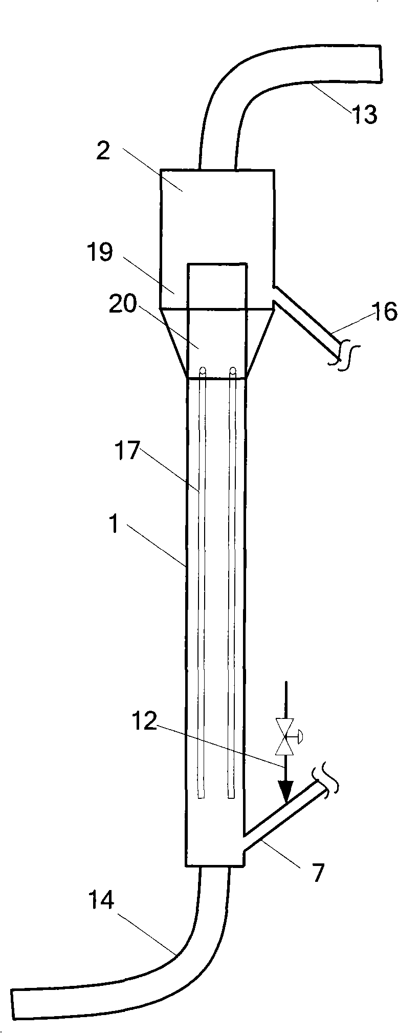
[0066] Use as attached figure 2 In the shown reactor, the disturbed flow zone 20 and the steady flow zone 19 are separated by a cylindrical baffle, and the bottom of the steady flow zone 19 communicates with the lower part of the reaction zone through a draft tube 17 . where the size of the reaction zone is 280×3600mm; the diameter of the expanded section of the settlement zone is 450mm, and the height is 1000mm; the size of the cylindrical baffle is 280×700mm, 6 diversion tubes in total, the sizes are 12×3000mm and 12×1500mm, staggered arrangement; the outer tube size of the downcomer is 280×2000mm, the inner filter tube is made of metal microporous membrane, with an average pore size of 0.2μm, such as Figure 6 The 7 wires shown are connected in parallel, and the size of each wire is 30×1000mm.

[0067] 160 liters of slurry containing solid particles is preliminarily introduced into the reactor, the particle size range of the slurry is 1-100 μm, and the superfic...

Embodiment 3

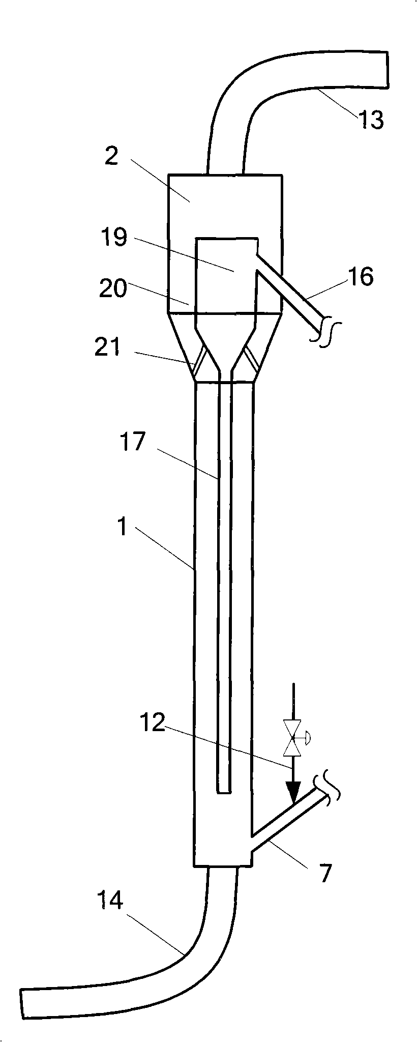
[0070] Use as attached image 3 In the shown reactor, the disturbed flow zone 20 and the steady flow zone 19 are separated by a conical cylindrical baffle, and the conical cylindrical baffle is fixed on the inner wall of the riser through a bracket 21. The bottom of the steady flow zone 19 communicates with the lower part of the reaction zone through the guide tube 17 . where the size of the reaction zone is 280×3600mm; the diameter of the expansion section of the settlement zone is 450mm, and the height is 1500mm; 150×750mm, the size of the guide tube is 40×2800mm; the size of the outer tube of the downcomer is 100×1200mm, the inner filter tube is made of metal microporous membrane with an average pore size of 1 μm, such as Figure 6 The 7 wires shown are connected in parallel, and the size of each wire is 30×1000mm.

[0071] Introduce 160 liters of slurry containing solid particles into the reactor in advance. The particle size range in the slurry is 1 to 100 μm. ...


PUM

PropertyMeasurementUnit
Outer diameteraaaaaaaaaa
Average pore sizeaaaaaaaaaa
Particle sizeaaaaaaaaaa

Abstract

The invention provides a slurry-bed loop reactor, comprising an ascending pipe and at least one downtake pipe 3, wherein, the ascending pipe consists of a reaction zone 1 and a settlement zone 2 with an expanded pipe diameter; an exhaust port 13 is arranged on the top of the settlement zone 2; the inside of each downtake pipe 3 is divided into a filtrate zone 5 and a slurry zone 6 by a filter medium 4, wherein, the filtrate zone 5 is communicated with a liquid discharge port 10; two ends of the slurry zone 6 are communicated with two ends of the ascending pipe 1, so the settlement zone 2 is separated into a steady flow zone 19 and a turbulent flow zone 20, wherein, the upper part of the steady flow zone 19 is communicated with the downtake pipe 3 through a pipeline 16; and the bottom of the steady zone 19 is directly communicated with the reaction zone 1 through an open pore 18 or through a draft tube 17. The slurry-bed loop reactor provided by the invention can realize continuous high-efficiency separation of solid catalyst particles, a liquid product and reacting gas, realize continuous discharging of a gas phase, a liquid phase and a solid phase, reduce turbulence of rising slurry from the reaction zone to settling particles in the settlement zone by separating the settlement zone into the turbulent flow zone and the steady flow zone, improve the separation efficiency of the settlement zone, and reduce the filtering load of the downtake pipe, thereby improving the treating capacity and the separation efficiency of the whole reactor, and prolonging the backsurge period.

Description

technical field [0001] The present invention relates to a device and method for separating solid particles from liquid, more specifically, to a device for continuous separation of liquid and solid particles in a slurry bed loop reactor and its application method. Background technique [0002] The slurry bed reactor is a commonly used gas-liquid (slurry) contact reaction equipment with a very high liquid storage capacity. For the catalytic reaction process with large reaction heat, the use of slurry bed reactor can effectively remove the reaction heat, realize the isothermal operation of the reactor, and ensure the normal operation of the reactor, so it has been widely used in today's chemical process. The slurry bed loop reactor is a high-efficiency heterogeneous reactor developed on the basis of the slurry bed bubbling reactor. In addition to all the advantages of the slurry bed bubbling reactor, the slurry bed loop reactor can also make the internal fluid circulate regula...

Claims


Application Information

Patent Timeline
IPC IPC(8): B01J8/22
Inventor 张占柱唐晓津胡立峰孟庆功侯栓弟王少兵毛俊义
Owner CHINA PETROLEUM & CHEM CORP
Why Eureka
Try Eureka