Shielding surface apparatus with space capable of being expanded

A technology of shielding surface and space, applied in the aerospace field, can solve the problems of structural surface density, configuration accuracy, and the storage rate cannot reach the use target, and achieves the effect of excellent storage rate, simple form, and reduced quality.

Inactive Publication Date: 2008-12-03
XIDIAN UNIV
View PDF1 Cites 24 Cited by
  • Summary
  • Abstract
  • Description
  • Claims
  • Application Information

AI Technical Summary

Problems solved by technology

Although some literatures disclose related space expandable structure technical solutions, the overall performance indicato

Method used


Image

  • Shielding surface apparatus with space capable of being expanded
  • Shielding surface apparatus with space capable of being expanded
  • Shielding surface apparatus with space capable of being expanded

Examples


example 1

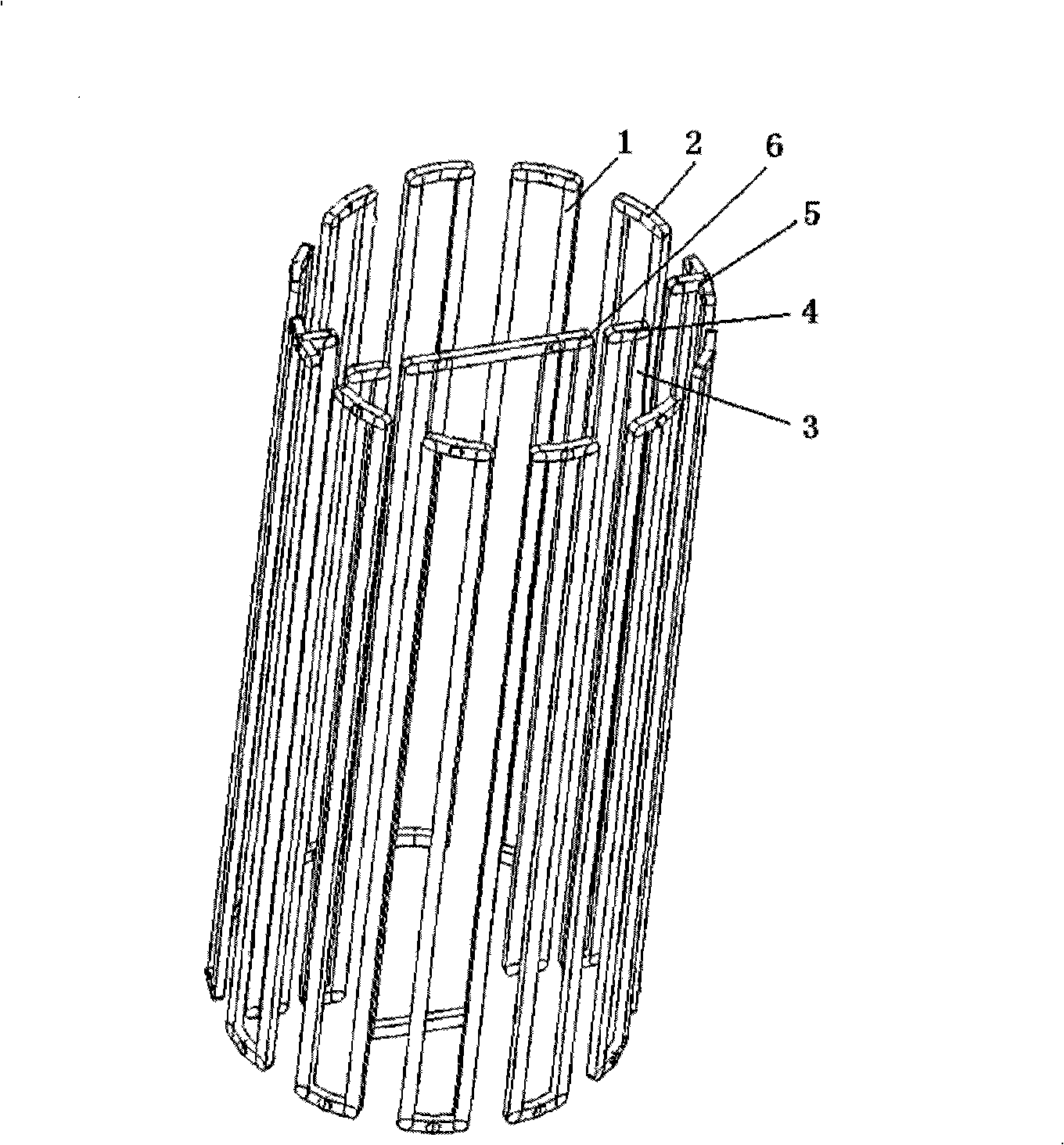
[0062] Example 1, a circular space with a diameter of 3m is deployed to place a planar support device.

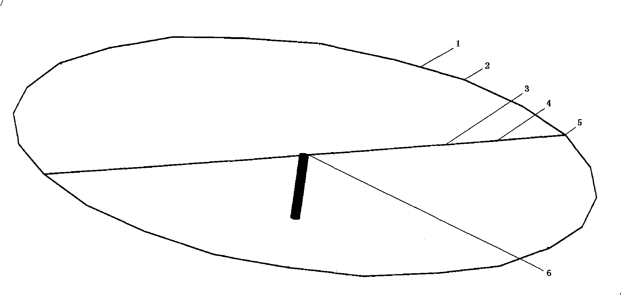
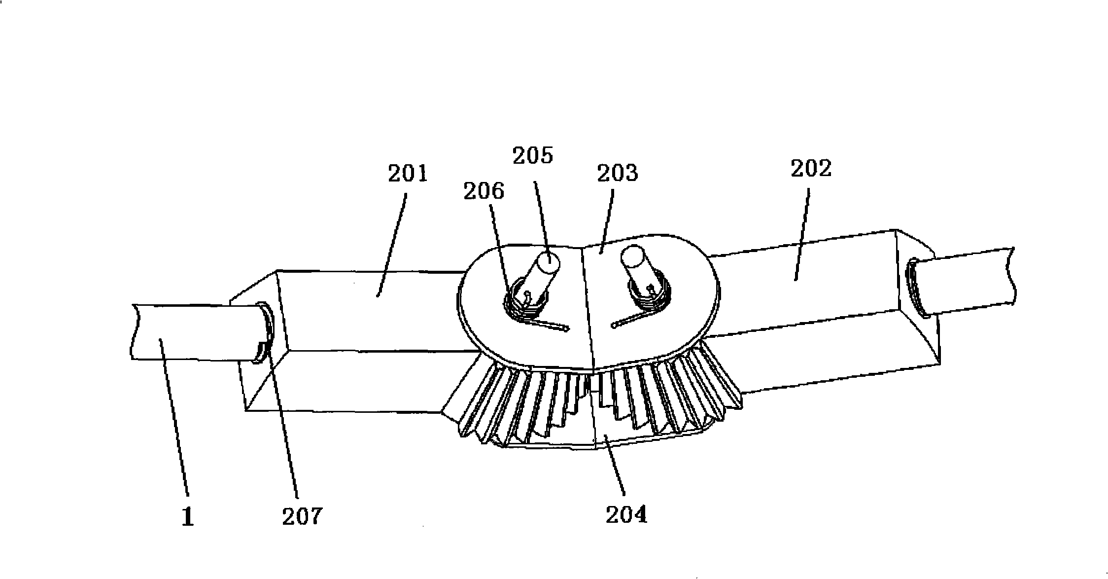
[0063] The collapsed state of the device is as figure 1 As shown, the expanded state is as figure 2 shown. There are 24 ring rods on the caliber ring structure, and a total of 8 rib rods on the two radial supporting rib structures. Both the ring bar and the rib bar are straight bars with a rectangular solid section of 0.006m×0.004m. The ring rod connection joint adopts image 3 The two conical synchronous gear mechanisms driven by the torsion spring shown in , the connection angle of the two synchronous mechanisms is 165 degrees. The rib-rod connection joint adopts Figure 5 Two cylindrical synchronous gear mechanisms driven by torsion springs shown in . The ring bar and the rib bar adopt the Figure 5 The groove structure shown in the figure is respectively assembled with the ring-rod connecting joint and the rib-rod connecting joint. ring structure and rib struct...

example 2

[0066] Example 2, a square space offset planar support device with a diameter of 8 m is deployed.

[0067] The collapsed state of the device is as Figure 9 shown. There are 4 ring rods on the caliber ring structure, and a straight rod with a rectangular solid section of 0.010m×0.008m is used. The ring rod adopts the Figure 5 The groove structure shown in the figure is assembled with the connecting joint of the ring rod to form an overall rigid structure that can be folded and unfolded. The ring rod connection joint adopts image 3 The two conical synchronous gear mechanisms driven by the torsion spring shown in , the connection angle of the two synchronous mechanisms is 90 degrees. ring structure through Figure 10 The installation holes 708 shown in the middle and outer connection joints 7 are assembled with the corresponding structures of the spacecraft. The entire structure of the device is made of aluminum alloy, which is packed into a cuboid of about 0.15m×0.15m×5...

example 3

[0069] Example 3, deploying a circular upright plane support device with a diameter of 20m, applied to the ground environment.

[0070] The unfolded state of the device is as Figure 11 shown. There are 36 ring rods on the caliber ring structure, which are straight rods with an outer diameter of Φ0.026m and an inner diameter of Φ0.020m; the central cylinder 8 adopts a round pipe with an outer diameter of Φ0.20m, an inner diameter of Φ0.18m and a height of 10m As a pillar, it is consolidated on the ground; the ring rod connection joint 2 adopts image 3 Shown structure, and can offer a hole on the outer splint 204 of this ring bar connection joint, be used for wearing flexible rope 9. The ring rod adopts the image 3 The threaded hole structure shown in is assembled with the ring-rod connection joint, and the connection angle of the two conical synchronous gear mechanisms is 170 degrees. The entire structure of the device is made of aluminum alloy, which is packed in a cyli...


PUM

PropertyMeasurementUnit
Outer diameteraaaaaaaaaa
The inside diameter ofaaaaaaaaaa
Outer diameteraaaaaaaaaa

Abstract

The invention discloses a spatial expandable ground plane device, comprising folding ring rods, ring rod connecting joints, folding rib rods, rib rod connecting joints, ring-rib connecting joints and rib frame connecting joints. The folding ring rods and the folding rib rods can be expanded from a vertical furled state to a horizontal working state through the ring rod connecting joints and the rib rod connecting joints. The ring-rib connecting joints and the rib frame connecting joints connect a ring structure with a rib structure to become a furled/expanded integral structure. A wire mesh or an aluminum-plated thin film is bound with the integral structure, so as to form the spatial expandable ground plane device. In a bound furled state, torsion springs in the ring rod connecting joints and the rib rod connecting joints store elastic potential energy; after binding is removed, the elastic potential energy of the torsion springs is transformed into driving energy so as to drive the ring rods and the rib rods to be expanded and locked automatically. The device has excellent comprehensive performance indexes of low surface density, high configuration precision and high ingathering rate, which can be used as an expandable support device in outer space or on ground.

Description

technical field [0001] The invention belongs to the field of aerospace technology, in particular to an expandable shielding surface device. It is mainly used in large-scale expandable devices such as sunshades and shielding surfaces in space, and can also be used in large-scale expandable devices on the ground for camouflage sheds, exhibition sheds, and temporary tents. Background technique [0002] With the continuous development of aerospace technology and the continuous expansion of aerospace applications, space large-scale deployable devices such as deployable antennas and solar panels have been more and more widely used, and even become one of the key components for the success of satellite applications. The limitations of launch vehicle size and carrying capacity, the high cost and high risk of aerospace applications, and the significant difference between the ground development environment and the space working environment all make the design of large space expandable...

Claims


Application Information

Patent Timeline
IPC IPC(8): B64G1/54E04H15/46H01Q1/28
Inventor 郑飞陈梅
Owner XIDIAN UNIV
Why Eureka
Try Eureka