Buttonholing machine
A sewing machine and buttonhole technology, applied to sewing machine components, program-controlled sewing machines, sewing machine control devices, etc., can solve the problems of troublesome cloth positioning, low production efficiency, and increased man-hours, so as to improve product quality, increase production efficiency, The effect of positioning improvement
- Summary
- Abstract
- Description
- Claims
- Application Information
AI Technical Summary
Problems solved by technology
Method used
Image
Examples
no. 1 approach
[0051] (first embodiment: overall structure)
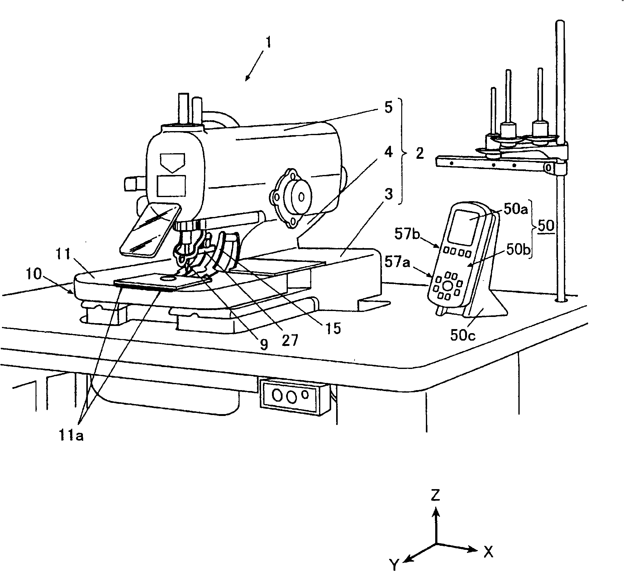
[0052] exist figure 1 Among them, the buttonhole overlock sewing machine 1 (hereinafter simply referred to as the sewing machine 1) is a sewing machine that forms, for example, Figure 22 A so-called round buttonhole having a straight line portion L and a substantially circular teardrop-shaped portion Q shown in (a), or a buttonhole such as Figure 22 For buttonhole cutouts such as linear buttonholes shown in (b), overlock sewing is performed on the edges of the cutouts.
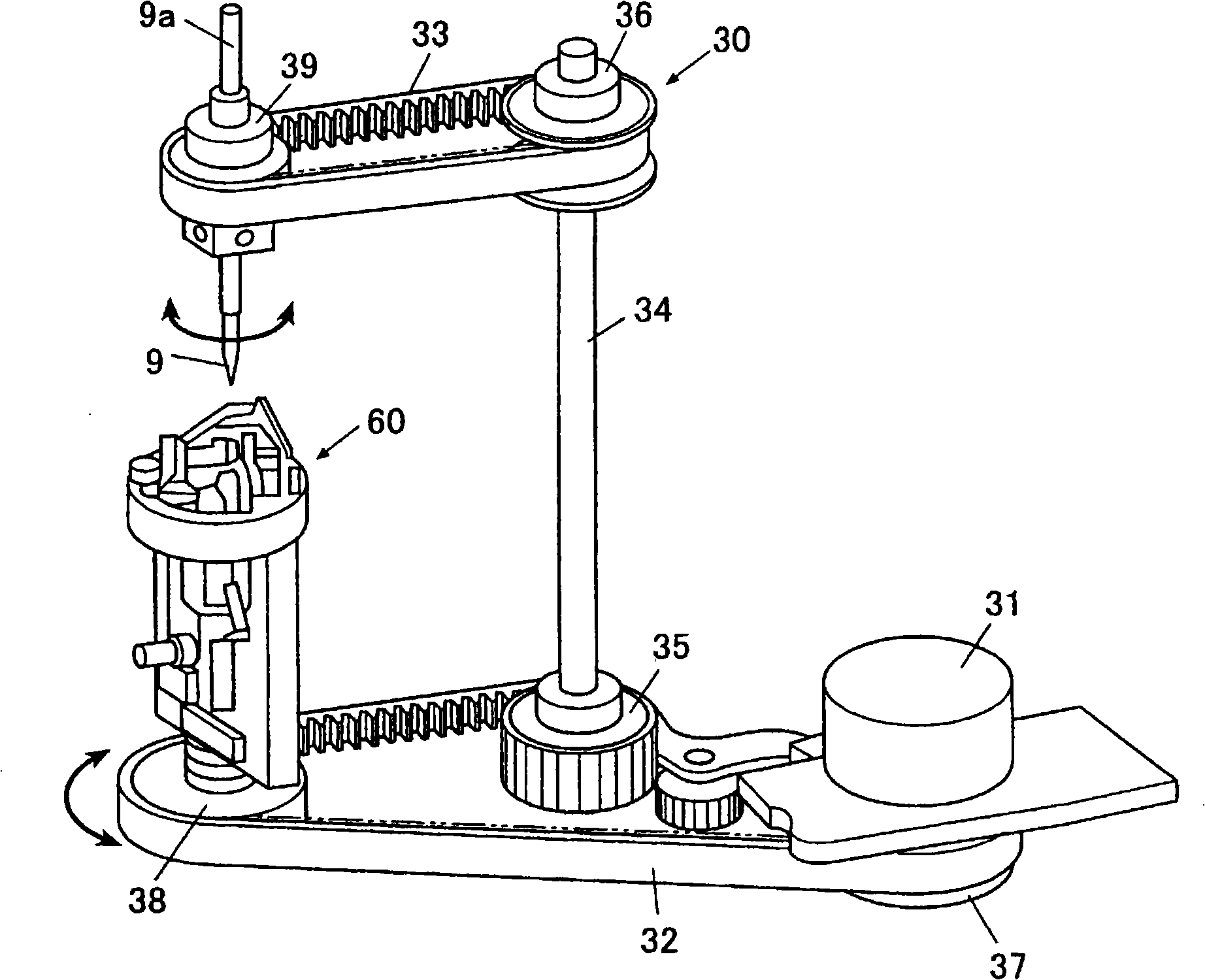
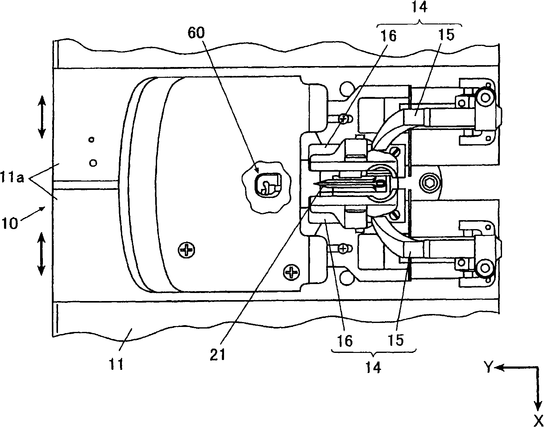
[0053] This sewing machine 1 has: a sewing machine frame 2; a cloth feeding mechanism 10, which has a feeding table 11 as a mounting table on which a cloth is placed above a base portion 3 of the sewing machine frame 2, and can be positioned in the XY direction (predetermined direction). Convey the cloth placed on the feed table 11; the cloth cutting mechanism 20 has a cutter support portion 27 and a cloth cutter 21 respectively arranged up and down facing each...
no. 2 approach
[0130] Below, according to Figure 13 to Figure 16 , the second embodiment using the present invention will be described in detail. In addition, in the second embodiment and the third embodiment described below, the same reference numerals are assigned to the same configurations as those of the above-mentioned first embodiment, and overlapping descriptions will be omitted.
[0131] The buttonhole overlock sewing machine 101 (hereinafter referred to as the sewing machine 101) according to the second embodiment is different from the above-mentioned first embodiment in that the camera unit 140 as the imaging unit is supported by the cloth cutter 21 and the cutter. The parts 27 are attached to the upper surface of the base part 3 at positions separated from the positions where the cloth cutting is performed in cooperation with each other.
[0132] Specifically, the camera unit 140 according to the present embodiment is arranged in parallel with the looper mechanism 60, and is loc...
no. 3 approach
[0148] Below, according to Figure 17 ~ Figure 19 , the third embodiment using the present invention will be described in detail.
[0149] The buttonhole overlock sewing machine 201 according to the third embodiment is different from the above-mentioned first and second embodiments in that a camera unit 240 serving as an imaging unit is mounted on the feeding table 211 . On the camera unit 240, the camera module 41 and the lighting device 46 respectively connected to the control unit 70 via cables not shown are provided, such as Figure 17 and Figure 18 As shown, they are installed inside the feeding table 211 by fixing bolts respectively. The camera module 41 is arranged so that the lens arranged facing upward is located on the extension line of the line approximately along the Y-axis direction connecting the cloth cutter 21 and the needle drop position of the sewing needle 9, and is positioned relative to the looper mechanism. 60 is located on the side of the operator's ...
PUM
 Abstract
Description
Claims
Application Information
 - R&D
- Intellectual Property
- Life Sciences
- Materials
- Tech Scout
- Unparalleled Data Quality
- Higher Quality Content
- 60% Fewer Hallucinations
Browse by: Latest US Patents, China's latest patents, Technical Efficacy Thesaurus, Application Domain, Technology Topic, Popular Technical Reports.
© 2025 PatSnap. All rights reserved.Legal|Privacy policy|Modern Slavery Act Transparency Statement|Sitemap|About US| Contact US: help@patsnap.com


