
Step type pneumatic digital valve

A digital valve, step-by-step technology, applied in the direction of sliding valves, valve details, safety valves, etc., can solve the problems of high cost, inability to directly realize digital control, complex structure of digital servo valves, etc., achieve low cost, improve external control characteristics, the effect of reducing the magnetic sink phenomenon

Inactive Publication Date: 2008-12-03
ZHEJIANG UNIV OF TECH
View PDF0 Cites 4 Cited by
  • Summary
  • Abstract
  • Description
  • Claims
  • Application Information

AI Technical Summary

Problems solved by technology

[0004] In order to overcome the shortcomings of existing digital servo valves, which are complex in structure, high in cost, and unable to directly realize digital control, the present invention provides a step-by-step pneumatic servo valve with simple structure, low cost, and direct digital control.

Method used


Image

  • Step type pneumatic digital valve
  • Step type pneumatic digital valve
  • Step type pneumatic digital valve

Examples


Embodiment Construction

[0022] The present invention will be further described below in conjunction with the accompanying drawings.

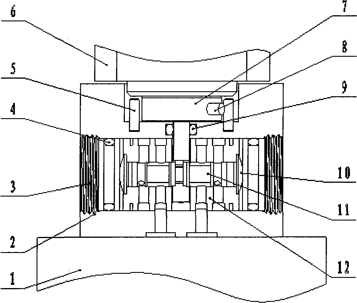
[0023] refer to Figure 1 ~ Figure 4 , a stepping pneumatic digital valve, including a valve seat 2, a valve body and a stepping motor 6, the valve body is located in the valve seat 2, the valve body includes a valve core 11 and a valve sleeve 12, and the valve core 11 can be It is mounted on the valve sleeve 12 to reciprocate left and right, the output shaft of the stepping motor 6 is connected to the input end of the eccentric mechanism 7 , and the output end of the eccentric mechanism 7 is linked with the valve core 11 .

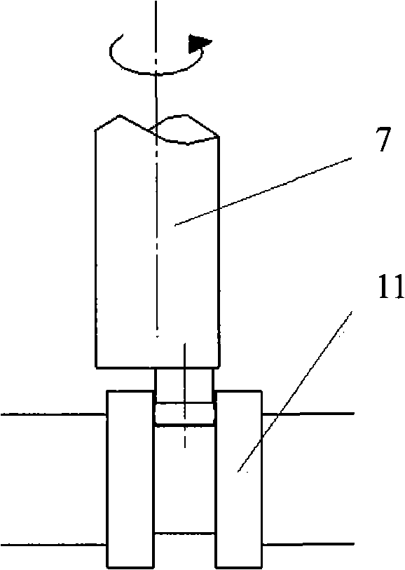
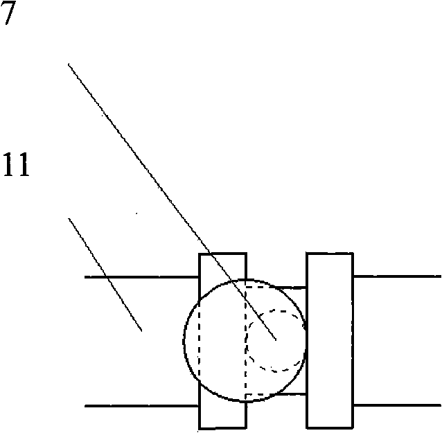
[0024] The eccentric mechanism 7 includes an input shaft and an output shaft eccentric to the center of the input shaft, the output shaft is installed at the lower end of the input shaft, and the output shaft is located between two baffle plates of the valve core 11 .

[0025] The interconnection relationship of valve seat 2, outer end cover 3, i...


PUM


Abstract

A stepwise pneumatic digital valve comprises a valve base, a valve body and a stepping motor. The valve body is positioned inside the valve base, the valve body comprises a valve core and a valve jacket, the valve core is installed on the valve jacket and capable of conducting reciprocating movement in left and right directions, the output shaft of the stepping motor is connected with the input end of an eccentric mechanism, and the output end of the eccentric mechanism is linked with the valve core. The inventive stepwise pneumatic digital valve has the advantages of simple structure and low cost; and can directly realize digital control.

Description

technical field [0001] The invention relates to a pneumatic digital servo valve, which is suitable for pneumatic control occasions. Background technique [0002] Pneumatic technology has developed rapidly in recent years. In the process of developing new products, foreign enterprises have continuously improved their product competitiveness and sought to win by quality. The original traditional pneumatic components have gradually been replaced by new pneumatic components due to backward structure, large volume, poor reliability and other reasons. [0003] For the field of high-speed and high-precision pneumatic control, the traditional electromagnetic drive servo valve is expensive, has high requirements on the environment, and the output pressure is small, so it cannot realize direct digital control in control. Therefore, the traditional servo valve is used as the pneumatic control of the experimental system. Components have certain defects. Contents of the invention [...

Claims


Application Information

Patent Timeline
IPC IPC(8): F16K31/04F16K37/00F16K3/22F16K17/36H02P1/16
Inventor 杨庆华慎石磊鲍官军吴佳艺
Owner ZHEJIANG UNIV OF TECH
Learn More