Amplitude phase measuring method

A measurement method, amplitude and phase technology, applied in the field of amplitude and phase measurement, can solve the problems of inverse cosine function can not get the negative phase, a large measurement error, phase offset and other problems, so as to achieve less harmonic interference, less noise interference, The effect of small amount of calculation

Inactive Publication Date: 2008-12-03
CHINA NAT OFFSHORE OIL CORP +1
View PDF0 Cites 32 Cited by
  • Summary
  • Abstract
  • Description
  • Claims
  • Application Information

AI Technical Summary

Problems solved by technology

[0018] From the formula (I), it can be seen that the phase difference can be obtained by seeking the inverse cosine function, and the solution result is between (0, π), but the phase difference of the electromagnetic wave induction logging signal is generally between (0, π/2), So in theory, this algorithm can meet the requirements, but the two channels of the same frequency signal in the induction logging

Method used


Image

  • Amplitude phase measuring method
  • Amplitude phase measuring method
  • Amplitude phase measuring method

Examples


Embodiment Construction

[0045] At first, explain the amplitude and phase measuring method of the present invention:

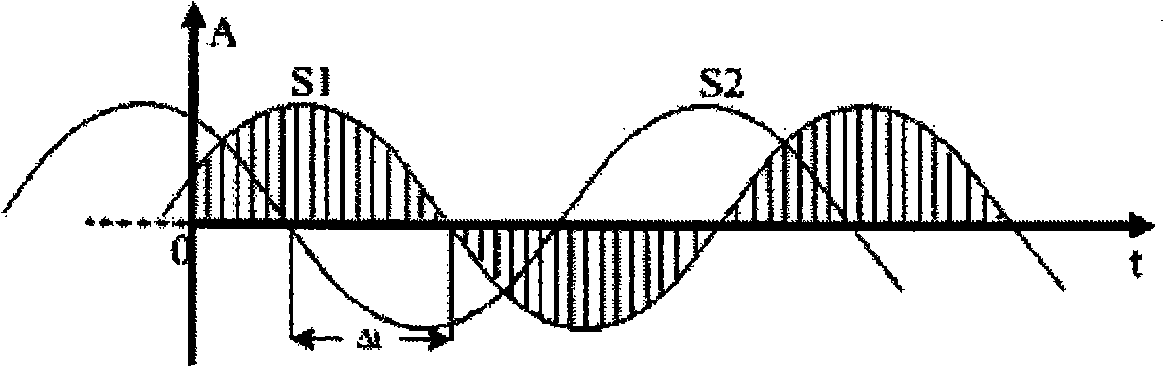
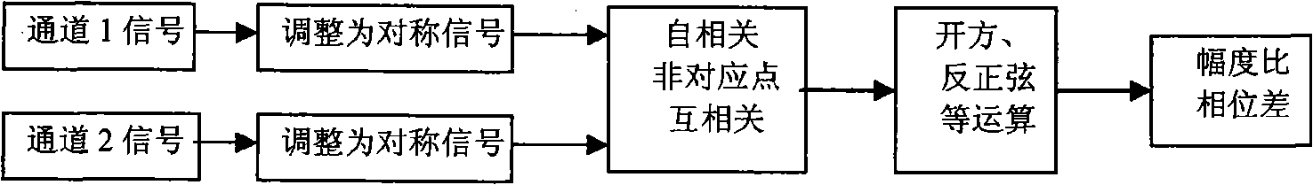
[0046] Such as figure 2 As shown, the process of a specific amplitude and phase measurement method of the present invention includes: first, the AD converter collects two channels of channel signals to be measured. Since the channel signals have a certain DC bias, the two channels of signals need to be adjusted to be symmetrical about zero potential signal, remove the DC bias. The adjusted signals are firstly subjected to autocorrelation calculations to obtain their respective amplitude values ​​and amplitude ratios. The two signals also need to perform cross-correlation calculations. The data collected by one of the signals is used to perform cross-correlation calculations with the data that starts after a quarter of the cycle of the other signal. Finally, the phase difference between the two signals is obtained by calculating the arcsine function.

[0047] Second, further elabora...


PUM


Abstract

The invention relates to a method for measuring an amplitude phase, which comprises the steps as follows: two paths of digital periodic signals are received and obtained, and each path of signal performs self-correlation calculation to obtain amplitude values respectively; after being delayed by one quarter cycle, one path of signal and the other path of signal perform mutual correlation calculation, the product of each amplitude value is divided by an obtained result, and then the phase difference between two paths of signals is obtained through the solution of an inverse sine function. The method has the advantages that the negative phase difference can be measured by a method for solving an arcsine instead of an arc cosine through shifting, thereby the requirement for the actual measurement of an electromagnetic wave logging instrument is met, the arithmetic mean value is further taken through a plurality of times of measurement, thus further enhancing measuring accuracy.

Description

technical field [0001] The invention relates to signal testing, in particular to a method for measuring amplitude and phase. Background technique [0002] At present, the phase difference measurement methods of sinusoidal signals mainly include zero-crossing detection method, spectrum analysis DFT method and correlation analysis method, as follows: [0003] (1) Zero-crossing detection method. The zero-crossing detection method calculates the time difference by judging the zero-crossing time of two signals of the same frequency, and then converts it into a corresponding phase difference. figure 1 It is the schematic diagram of the zero-crossing detection method, and the phase difference calculation formula is: [0004] [0005] Among them, Δt is the time difference between the zero-crossing points of the two detected signals, and T is the signal period. The error of the zero-crossing detection method is related to the number of digits of the data acquisition card, the s...

Claims


Application Information

Patent Timeline
IPC IPC(8): G01R25/00G01R19/00G01V3/30
Inventor 师奕兵张雷岳峰
Owner CHINA NAT OFFSHORE OIL CORP
Why Eureka
Try Eureka