

Hydraulic control system and apparatus for split positioning of ship body
A technology of hydraulic control system and hull, applied in ship parts, ship construction, transportation and packaging, etc., can solve the problems of reducing the effective operation time of cranes, low positioning accuracy, high labor intensity, etc., to eliminate subversion interference and run smoothly. , the effect of reducing labor intensity
- Summary
- Abstract
- Description
- Claims
- Application Information
AI Technical Summary
Problems solved by technology
Method used
Image

Examples
Embodiment Construction
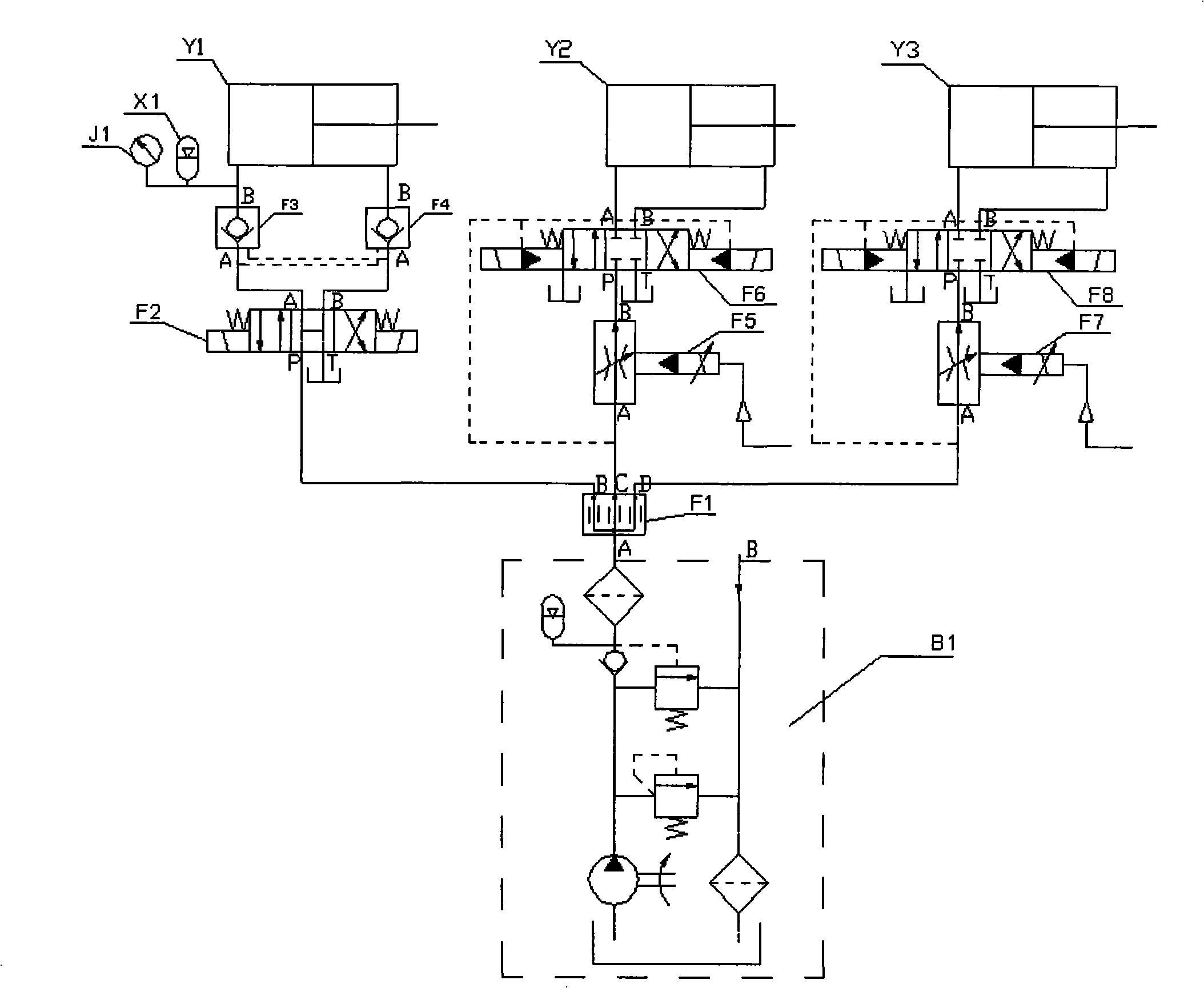
[0023] Further illustrate the present invention below in conjunction with accompanying drawing.
[0024] Such as figure 1 As shown, the hydraulic control system for segmental positioning of the hull of the present invention includes a constant pressure oil source pump station B1, a first hydraulic cylinder Y1, a second hydraulic cylinder Y2, a third hydraulic cylinder Y3, a first hydraulic control check valve F3, second hydraulic control check valve F4, first proportional flow valve F5, second proportional flow valve F7, first electro-hydraulic directional valve F6, second electro-hydraulic directional valve F8, three-position four-way solenoid valve F2 and diverter valve F1;
[0025] The piston rod of the first hydraulic cylinder Y1 moves up and down, and a displacement sensor is provided; the oil port of the rodless chamber of the first hydraulic cylinder Y1 is connected to the B port of the first hydraulic control check valve F3, and the oil port of the rod chamber Connec...
PUM
 Abstract
Description
Claims
Application Information