Power transport mechanism and plasma auxiliary chemical vapor deposition apparatus using the same

A chemical vapor deposition, power transmission technology, applied in gaseous chemical plating, metal material coating process, coating and other directions, can solve the problems of reducing the qualified rate, large floor space, high cost, and achieve the effect of improving competitiveness

Inactive Publication Date: 2008-12-10
IND TECH RES INST
View PDF1 Cites 9 Cited by
  • Summary
  • Abstract
  • Description
  • Claims
  • Application Information

AI Technical Summary

Problems solved by technology

However, picking and placing chips manually not only limits the overall production efficiency, but also easily reduces the pass rate due to contamination of the chips
[0005] Recently, there are also those who use robotic arms for automatic pick-and-place, but not only the floor space required for the machine is large, but also the cost is high

Method used


Image

  • Power transport mechanism and plasma auxiliary chemical vapor deposition apparatus using the same
  • Power transport mechanism and plasma auxiliary chemical vapor deposition apparatus using the same
  • Power transport mechanism and plasma auxiliary chemical vapor deposition apparatus using the same

Examples


Embodiment Construction

[0082] In order to enable a further cognition and understanding of the features, purposes and functions of the present invention, the related detailed structure and design concept of the device of the present invention are described below:

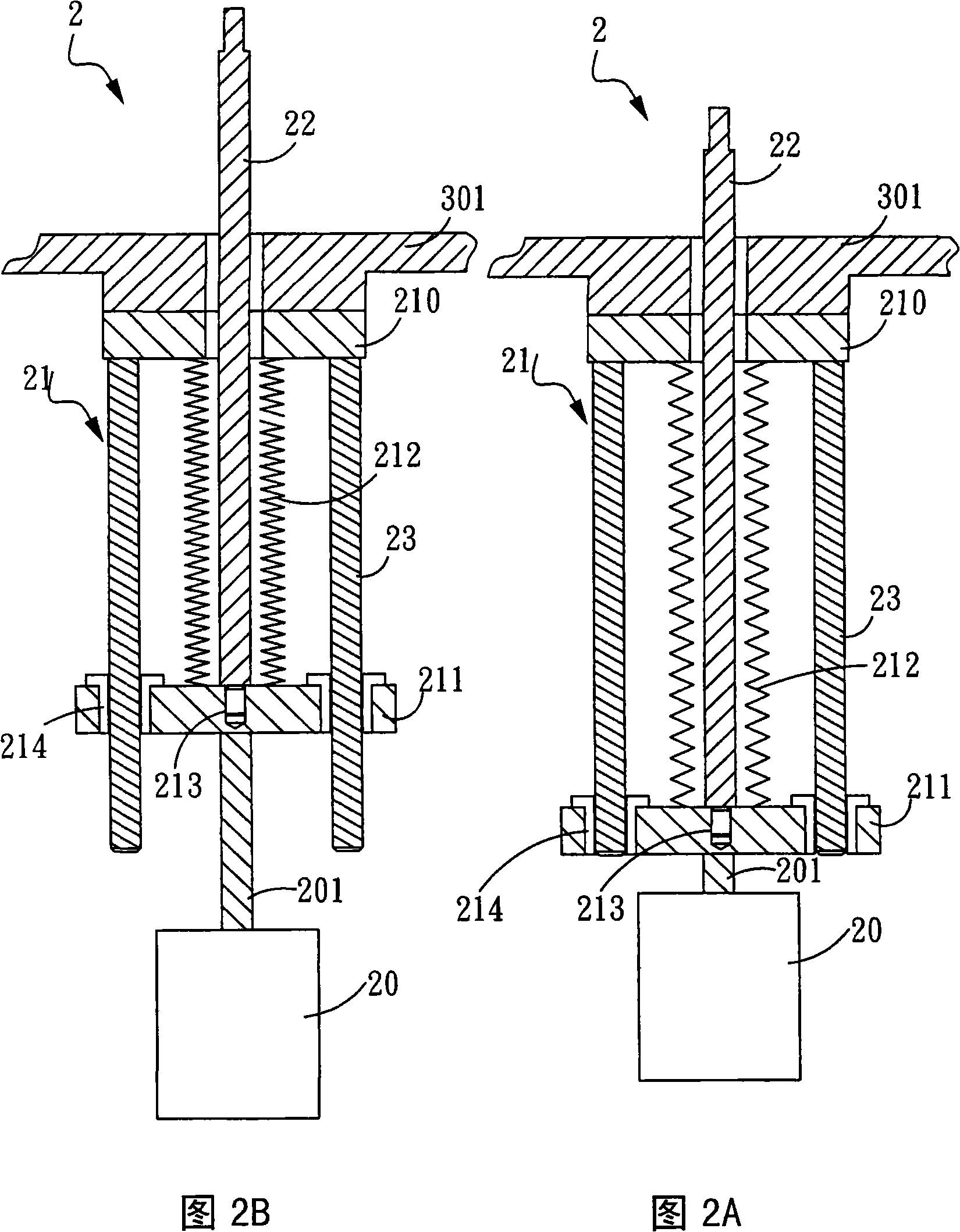
[0083] Refer to FIG. 2A and FIG. 2B, which are schematic cross-sectional views of an embodiment of the power transmission mechanism of the present invention. As shown in FIG. 2A, the power transmission mechanism 2 includes a power unit 20, an airtight telescopic unit 21 and a supporting column 22. The power unit 20 can provide power, and the power unit 20 can be a pneumatic cylinder, a motor, or other components with power output capabilities. In this embodiment, the power unit 20 is a pneumatic cylinder. The airtight telescopic unit 21 is connected to the power unit 20 to receive the power provided by the power unit 20. The support column 22 is disposed in the airtight telescopic unit 21, and one end of the support column 22 extends to the ou...


PUM


Abstract

The invention discloses a power transmission mechanism, which combines airtight and flexible components with a power unit to generate displacement motion in a given direction. Besides, this invention further provides a plasma-assisted chemical vapor deposition device which makes use of the power transmission mechanism as a mechanism for controlling the movement of a component to be processed so that the plasma-assisted chemical vapor deposition device can be combined with an automatic transmission device so that the in and out of a chip are automated. In addition, the plasma-assisted chemical vapor deposition device is further provided with a lifting and adjusting unit and a position marking unit to allow an operator to adjust the space between an upper electrode and a lower electrode according to the requirements of a manufacture process and the operator of the machine station to clearly control the space between the upper electrode and the lower electrode inside the cavity body from the outside of the cavity body.

Description

Technical field [0001] The present invention relates to a power transmission mechanism, in particular to a power transmission mechanism that uses components with airtight and telescopic characteristics to be combined with a power unit to generate a displacement movement in a specific direction, and uses the power transmission The mechanism is a plasma-assisted chemical vapor deposition device that controls the up and down movement of the chip, so that the transfer and placement of the chip can be automated, thereby improving the quality and productivity. Background technique [0002] IC semiconductors and solar photovoltaic products have been closely related to people's daily life. However, the equipment used in the production of these products today, such as Plasma-Enhanced Chemical Vapor Deposition (PECVD), is still monopolized by several foreign manufacturers. At the same time, the machines produced by these large factories are too expensive on the one hand, and on the other h...

Claims


Application Information

Patent Timeline
Patent Type & Authority Applications(China)
IPC IPC(8): C23C16/513C23C16/52
Inventor 江源远陈冠州董福庆
Owner IND TECH RES INST
Why Eureka
Try Eureka