

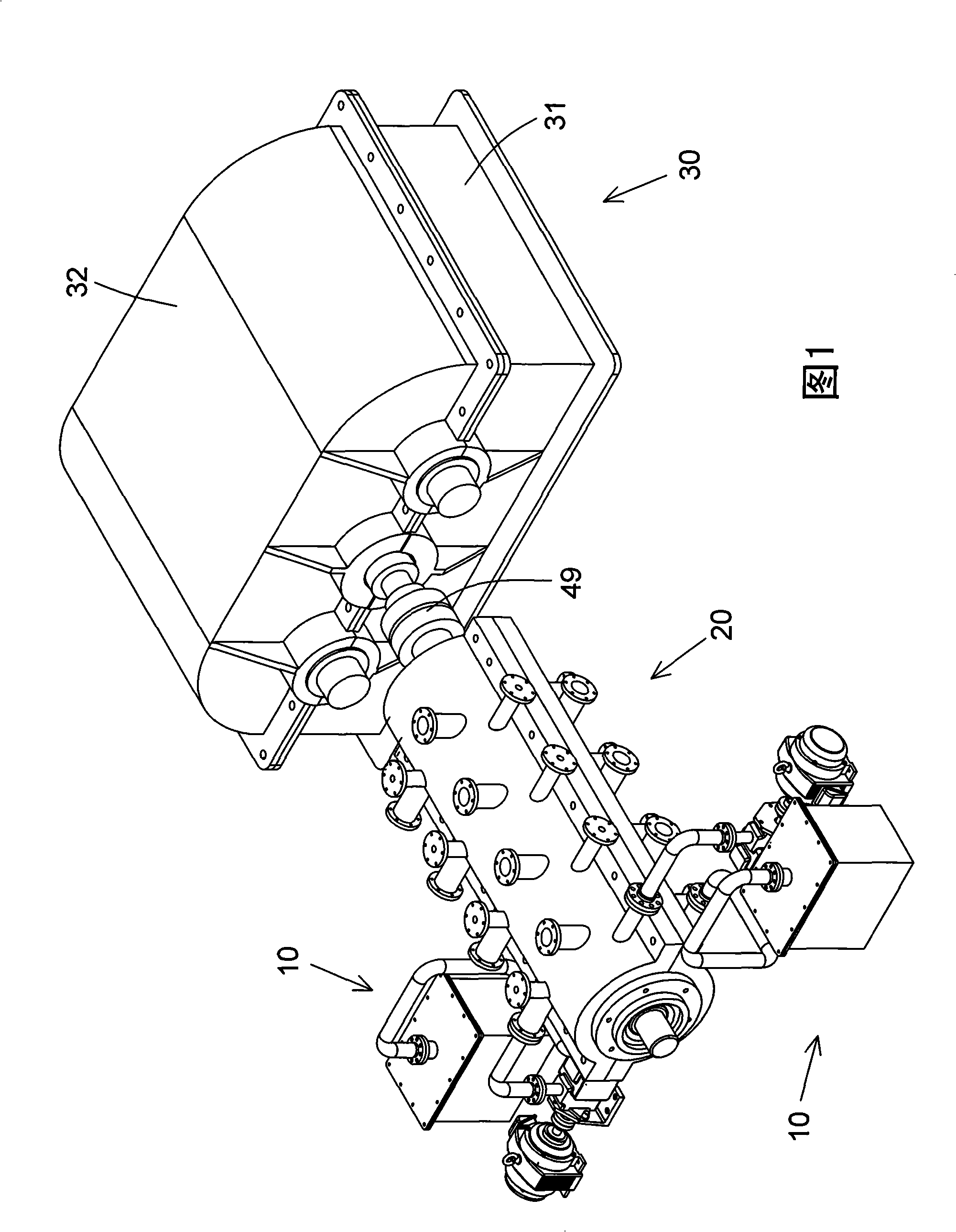
Hydraulic power acceleration equipment
A hydraulic power and equipment technology, applied in mechanical equipment, engine components, machines/engines, etc., can solve the problems of high cost, limited output power of electric motors, unbalanced pressure, etc., and achieve a wide range of applications, good operation stability and smooth The effect of load equalization
- Summary
- Abstract
- Description
- Claims
- Application Information
AI Technical Summary
Problems solved by technology
Method used
Image

Examples
Embodiment Construction
[0027] Label in the figure
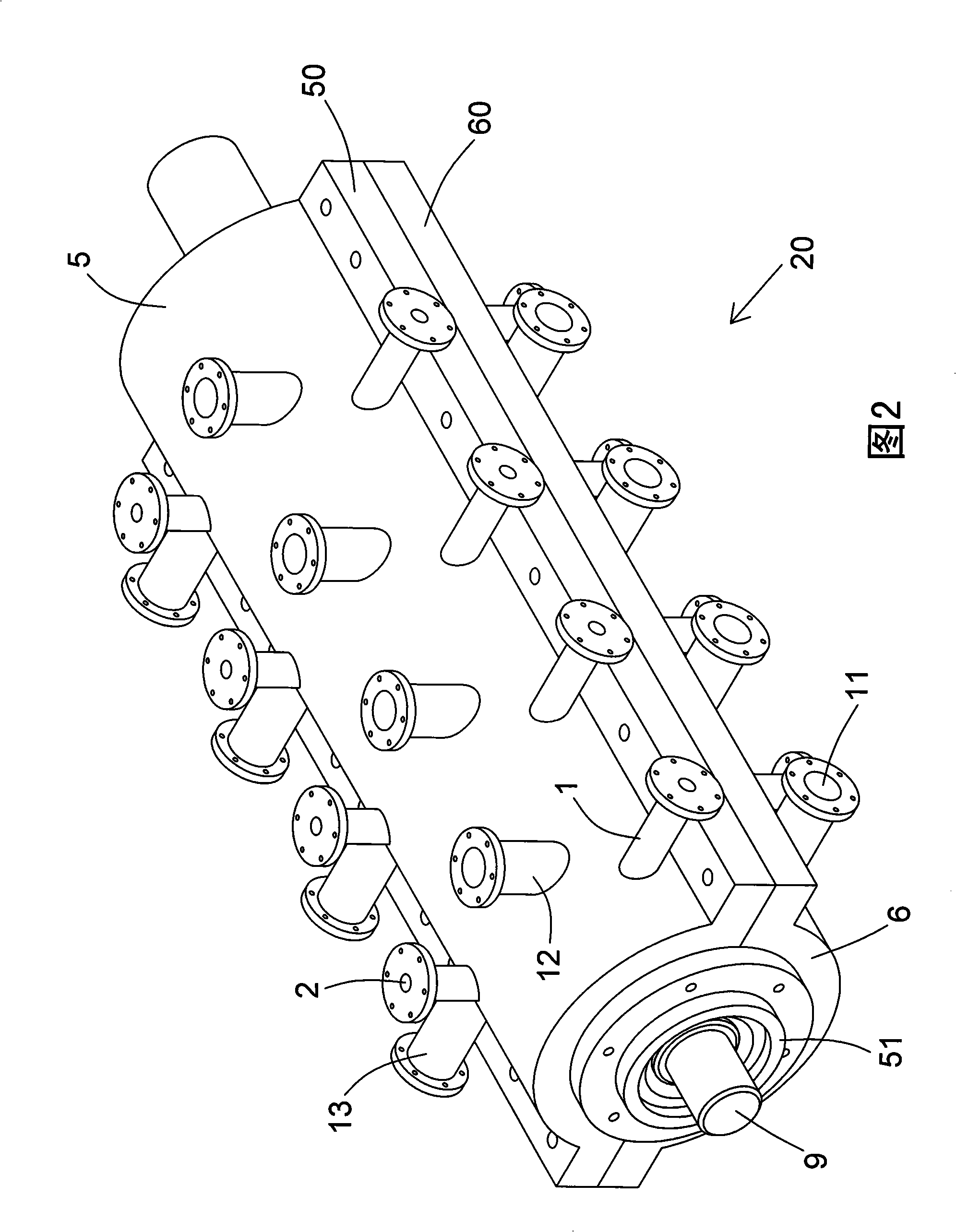
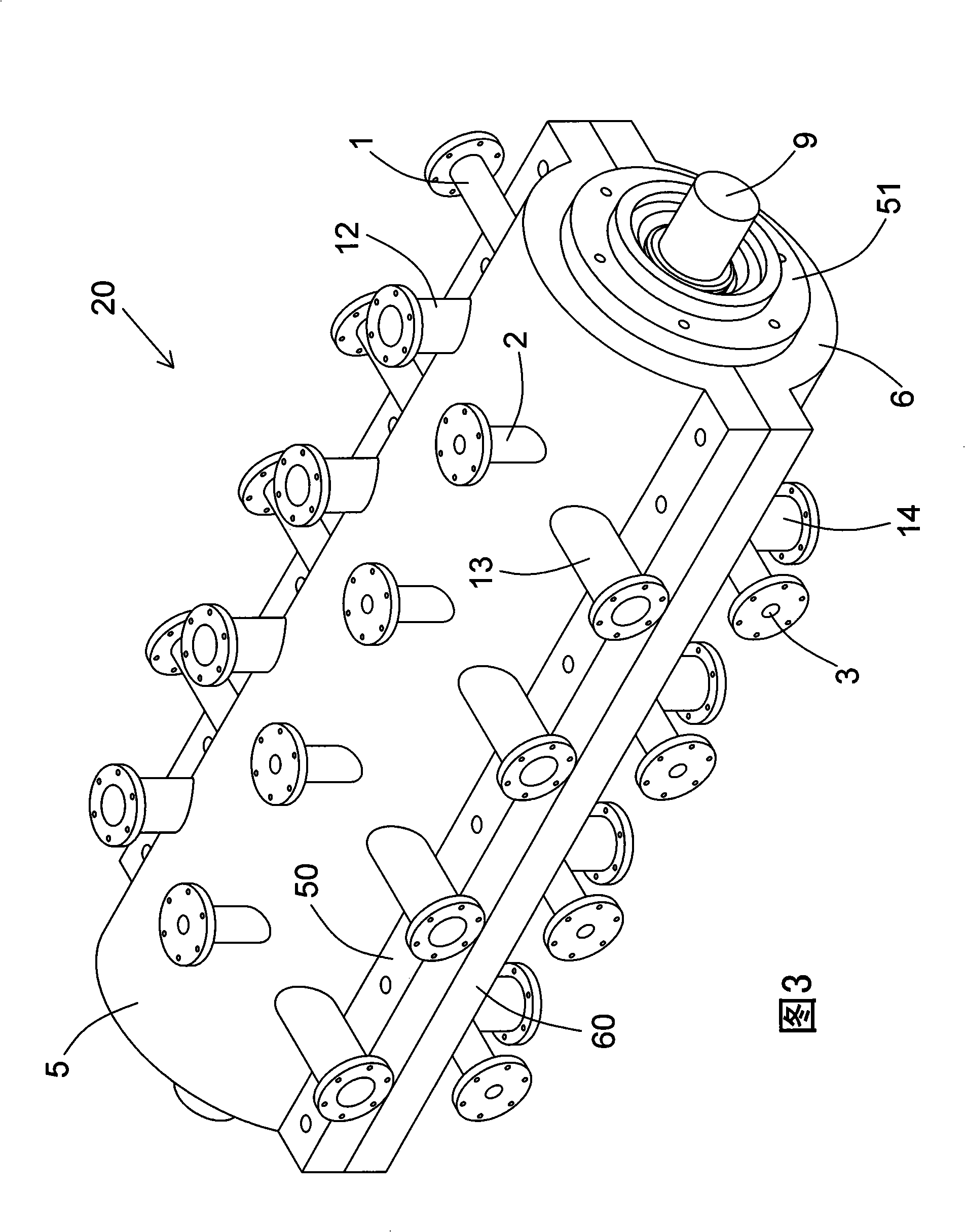
[0028] 1 No. 1 oil inlet channel 2 No. 2 oil inlet channel 3 No. 3 oil inlet channel
[0029] 4 No. 4 oil inlet channel 5 Upper cover 6 Lower cover
[0030] 7 rotor 8 impeller 9 power shaft 10 hydraulic oil circuit system
[0031] 11 No. 1 oil outlet channel 12 No. 2 oil outlet channel
[0032] 13 No. 3 oil outlet channel 14 No. 4 oil outlet channel
[0033] 15 upper groove 16 lower groove 17 ring groove 18 teeth
[0034] 19 spacer ring 20 hydraulic power machine
[0035] 21 No. 1 cylinder 22 No. 2 cylinder 23 No. 3 cylinder 24 No. 4 cylinder
[0036] 25 electric motor 26 oil pump 27 oil tank 28 oil inlet pipe
[0037] 29 oil return pipe 30 speed increase box 31 box body 32 box cover
[0038] 33 Input shaft 34 Output shaft 35 Left drive shaft 36 Right drive shaft
[0039] 37 Support seat 38 Left front bearing 39 Left rear bearing 40 Gear set
[0040] 41 Right front bearing 42 Right rear bearing 43 Input gear 44 Output gear
[0041] 45 lef...
PUM
 Abstract
Description
Claims
Application Information