
Hot-plug fan and its terminal base

A terminal block and hot-swappable technology, applied in the field of hot-swappable fans, can solve the problems of non-replacement, low fan and system assembly margin, poor assembly pass rate, etc., and achieve the effect of improving the assembly margin

Inactive Publication Date: 2008-12-10
DELTA ELECTRONICS INC
View PDF0 Cites 4 Cited by
  • Summary
  • Abstract
  • Description
  • Claims
  • Application Information

AI Technical Summary

Problems solved by technology

However, when the fan fails, the above-mentioned connection method cannot be replaced while the electronic system continues to operate
What's more, the shape and position of the tubular terminal block and the corresponding terminal block on the system must have high accuracy, so the assembly margin between the fan and the system is very low, resulting in poor assembly yield

Method used


Image

  • Hot-plug fan and its terminal base

Examples


Embodiment Construction

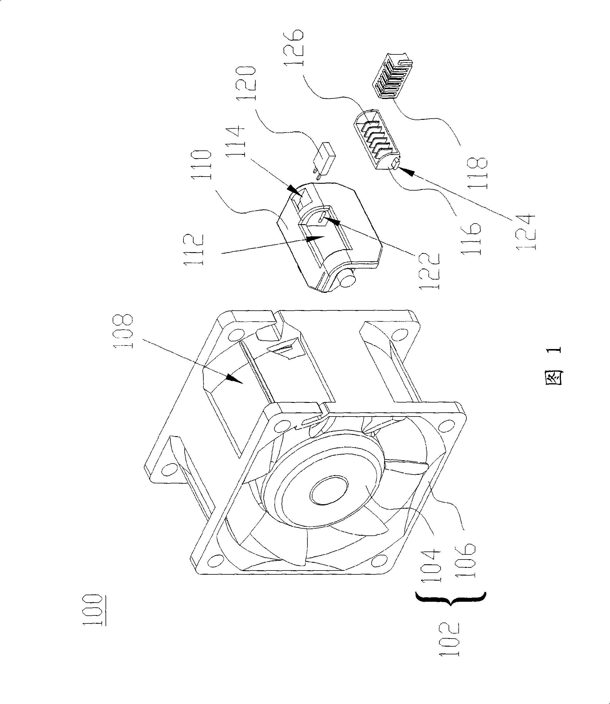
[0020] FIG. 1 is a schematic diagram illustrating a hot-swap fan 100 according to a first preferred embodiment of the present invention. The hot-swappable fan 100 of this preferred embodiment is a fan that can be hot-swapped in a system at any time. The hot-swap fan 100 includes a fan body 102 , at least one first terminal base 110 and at least one second terminal base 116 . The hot-swap fan 100 can be an axial fan or a centrifugal fan.

[0021] The fan body 102 has at least one impeller 104 and at least one fan frame 106 . The impeller 104 is accommodated in the fan frame 106 , and the fan frame 106 has at least one accommodating groove 108 around its periphery. The fan body 102 can have a control circuit board to control the operation of the impeller 104 . In addition, the control circuit board may not be required, and the impeller 104 is electrically connected to the system (or external device) via the terminals of the second terminal base 116 to receive signals from the...


PUM


Abstract

The invention discloses a hot-swap fan which comprises a fan, at lest a first terminal block and at least a second terminal block. The fan is provided with at least an impeller and at least a fan frame. The impeller is arranged in the fan frame, and the circumference of the fan frame is provided with at least a first containing groove. The first terminal block is arranged and fixed in the first containing groove, and is provided with at least a second containing groove. The second terminal block is arranged in the second containing groove, and can float in the second containing groove.

Description

technical field [0001] The invention relates to a fan, in particular to a self-floating terminal base and a hot-plug fan with the terminal base. Background technique [0002] As the function and operating speed of the electronic system increase, the heat generated by it also increases relatively. In order to maintain the normal operation of the electronic system, the existing technology is to configure a fan as a heat dissipation device to force the heat dissipation through the airflow, so that the electronic system can be maintained in a normal state. operating temperature. [0003] A conventional fan is connected to a system (such as a motherboard or a circuit board) through a set of wires to receive power and drive signals to operate. The group of wires is connected to the system by welding, or the group of wires is connected to a tubular terminal base with tubular terminals, and then connected to the system through the tubular terminal base. However, when the fan fails...

Claims


Application Information

Patent Timeline
Patent Type & Authority Applications(China)
IPC IPC(8): F04D25/08H01R9/00H01R13/73
Inventor 陈建昌余政书陶鹏举
Owner DELTA ELECTRONICS INC
Learn More