
Method and device for high-precision large-range measuring size of optical fiber

A technology for measuring optical fibers and a large range, which is applied in the directions of measuring devices, optical demodulation, and optical waveguide coupling, etc. It can solve the problems of high cost, difficulty in practical use, inability to achieve high precision and large measurement range at the same time, and achieve low cost , Strong mechanical disturbance performance and strong resistance to external temperature fluctuations

Inactive Publication Date: 2008-12-10
ZHEJIANG UNIV
View PDF0 Cites 19 Cited by
  • Summary
  • Abstract
  • Description
  • Claims
  • Application Information

AI Technical Summary

Problems solved by technology

[0003] Traditional optical fiber length measurement instruments are based on fiber optic reflectometers, including optical time domain reflectometer (OTDR), optical frequency domain reflectometer (OFDR), optical coherent reflectometer (OCDR), these methods or require extremely short pulse laser The cost of light source and extremely high-speed photoelectric probe is relatively high; or it cannot meet the requirements of high precision and large measurement range at the same time, so it is difficult to be practical

Method used


Image

  • Method and device for high-precision large-range measuring size of optical fiber
  • Method and device for high-precision large-range measuring size of optical fiber
  • Method and device for high-precision large-range measuring size of optical fiber

Examples


Embodiment Construction

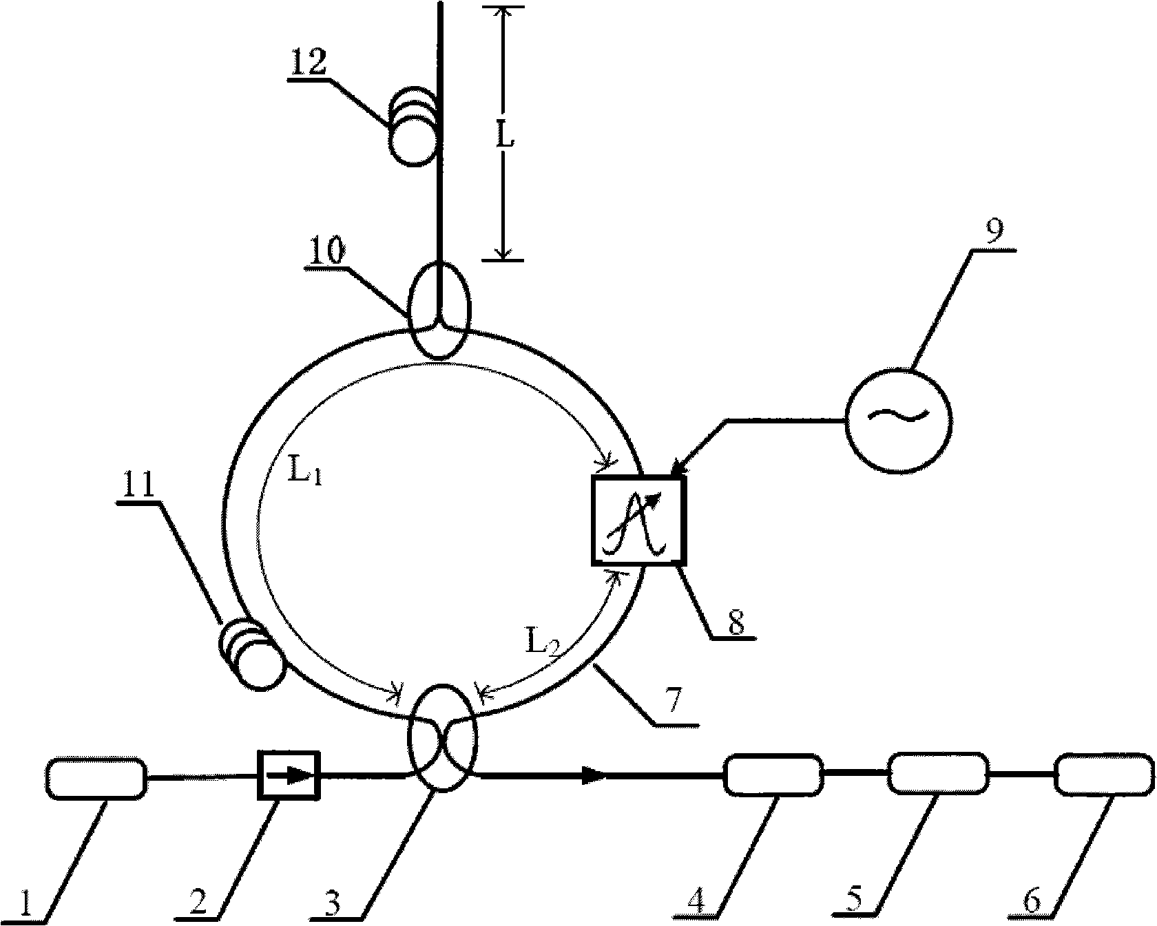
[0022] Such as figure 1 As shown, the semiconductor laser 1 is optically connected to the input port of the four-port 3-dB fiber coupler 3 through the fiber isolator 2, and the output port of the four-port 3-dB fiber coupler 3 is optically connected to the input port of the photodiode 4. The output end of the diode 4 is electrically connected to the input end of the data acquisition card 5 , and the output end of the data acquisition card 5 is electrically connected to the FFT analyzer 6 . The other two ports of the four-port 3-dB fiber optic coupler 3 are connected by a single-mode optical fiber, and the single-mode optical fiber is divided into two sections by the acousto-optic modulator 8, which are respectively the single-mode optical fiber 11 of the measurement section and the single-mode optical fiber 7 of the connecting section, The length is L 1 and L 2 , L 1 >>L 2 . The electrical drive signal port of the acousto-optic modulator 8 is electrically connected to the...


PUM


Abstract

The invention relates to a method and a device for measuring an optical fiber length with high precision and large range. An acoustooptic modulator is connected with a Sagnac loop. The acoustooptic modulator is asymmetrically arranged in the Sagnac loop. One end of the optical fiber the length of waiting to be detected is connected with the Sagnac loop by a three-port 3-dB optical fiber coupler and the other end is a free end which can generate end surface reflection; the acoustooptic modulator is driven by a RF signal with variable frequency; when the frequency of the RF signal is changed, the transmittivity of the Sagnac loop is changed; the change of the transmittivity is relevant with the length of the optical fiber to be measured; the change of the transmittivity is measured by a photodiode; the output end of the photodiode is connected with a data collection card; the data collected by the collecting card is transmitted to a computer. The length of the optical fiber to be measured is obtained by fast Fourier change and relevant operations. The method and the device for measuring an optical fiber length with high precision and large range overcome the defects of being incapable of simultaneously meeting the demand of measuring with high precision and large range and having a relative lower cost. As the optical fiber to be measured is connected with the Sagnac loop, the anti-external temperature fluctuation and the mechanical anti-disturbance performances of the device are high.

Description

technical field [0001] The invention belongs to the field of optical fiber optics technology, and relates to optical fiber length measurement technology, especially for optical fiber communication, optical fiber sensing and other application fields that require fast, high-precision and large-scale measurement of optical fiber length. A method for detecting the length of an optical fiber caused by the asymmetric effect of the interferometer structure caused by the frequency of light waves and a device for realizing the method. Background technique [0002] In the field of fiber optics, especially in fiber optic communications, it is of great significance to develop fast, high-precision and large-scale methods for measuring the length of optical fibers and low-cost equipment. [0003] Traditional optical fiber length measurement instruments are based on fiber optic reflectometers, including optical time domain reflectometer (OTDR), optical frequency domain reflectometer (OFDR)...

Claims


Application Information

Patent Timeline
Patent Type & Authority Applications(China)
IPC IPC(8): G01B11/02G02F1/35G02F2/02G02B6/28G02F1/03
Inventor 何赛灵周斌管祖光夏天豪
Owner ZHEJIANG UNIV
Learn More