Projection optical system

A technology of projection optical system and positive focal power, which is applied in the field of projection optical system, can solve the problems of increasing the difficulty of optical installation and adjustment, increasing the manufacturing cost, and the difficulty of designing the structure of the mask and silicon wafer movement positioning transmission structure, etc., to achieve the reduction of optical The overall length, large space layout, and the effect of reducing the difficulty of optical installation and adjustment

Active Publication Date: 2008-12-10
SHANGHAI MICRO ELECTRONICS EQUIP (GRP) CO LTD
View PDF2 Cites 7 Cited by
  • Summary
  • Abstract
  • Description
  • Claims
  • Application Information

AI Technical Summary

Problems solved by technology

The increase in the number of lenses will lead to an increase in manufacturing costs and also increase the difficulty of optical adjustment
In addition, according to the embodiment provided by the previous patent, the working distances of the object space and the image space realized by this solution are less than 64mm and 14mm respectively, and the small working distances of the object space and the image space allow the movement positioning and transmission of the mask and the silicon wafer The structural design of the structure etc. brings great difficulties

Method used


Image

  • Projection optical system
  • Projection optical system
  • Projection optical system

Examples


Embodiment Construction

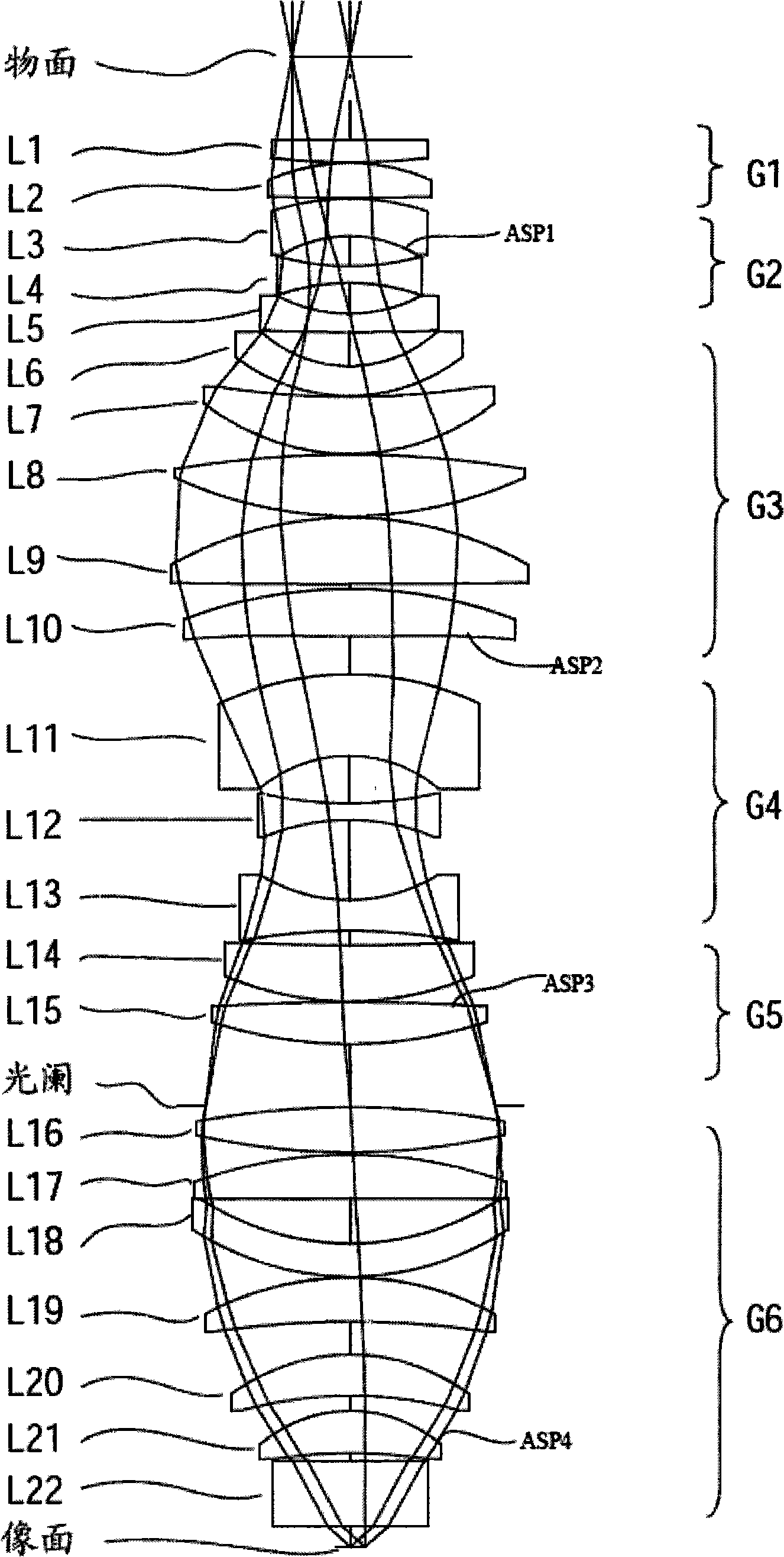
[0017] The present invention provides a kind of bi-telecentric projection optical system (object-side and image-side telecentric errors are all less than 1mrad), which uses a negative thick meniscus lens to correct field curvature and astigmatism (field curvature and astigmatism are both within ± 2nm), while obtaining better distortion and imaging quality, and providing a larger object space and image space working distance: object space 68mm, image space 16mm.

[0018] like figure 1 As shown, the projection optical system of the present invention includes 22 lenses and is divided into six lens groups G1 to G6 and arranged in sequence between the object plane and the image plane. The first lens group G1 , the third lens group G3 , the fifth lens group G5 and the sixth lens group G6 have positive refractive powers, and the second lens group G2 and the fourth lens group G4 have negative refractive powers.

[0019] The first lens group G1 includes two lenses L1-L2, wherein the l...


PUM

PropertyMeasurementUnit
thicknessaaaaaaaaaa
wavelengthaaaaaaaaaa
radiusaaaaaaaaaa

Abstract

The invention provides a projection optical system which is formed by that twenty-two lenses which are divided into six lens groups are orderly arranged between an object plane and an image plane; wherein, the first, the third, the fifth and the sixth lens groups have positive focal power, and the second and the fourth lens groups have negative focal power. A negative meniscus lens is used in the projection optical system to correct the field curvature and the astigmatism and control the field curvature and astigmatism within the range of from minus 2nm to plus 2nm, and favorably realizes double telecentricity of the object space and the image space is better realized through introducing four aspheric surfaces, and thus both the telecentric errors of the object space and the image space are less than 1mrad. The projection optical system has larger working distance of the object space and the image space, and thereby providing a larger space for arranging a workbench, a reticle stage and an alignment system thereof.

Description

technical field [0001] The invention relates to a projection optical system for semiconductor lithography and photoplate making, in particular to a double telecentric projection optical system. Background technique [0002] Photolithography is a very important process in the semiconductor manufacturing process. The exposure device used in the photolithography process projects the pattern of the mask on the photosensitive substrate such as dry film through the projection optical system and then exposes it. The exposure quality is Good or bad will have a great impact on the subsequent etching process. With the improvement of the integration level of semiconductor components, the requirements of the semiconductor manufacturing process on the resolution of the projection optical system have also increased. In order to meet the requirements for the resolution of the projection optical system, the exposure device needs to shorten the wavelength of illumination light (light for ex...

Claims


Application Information

Patent Timeline
Patent Type & Authority Applications(China)
IPC IPC(8): G02B9/62G02B1/02G02B27/00G03F7/20
Inventor 储兆祥李铁军
Owner SHANGHAI MICRO ELECTRONICS EQUIP (GRP) CO LTD
Why Eureka
Try Eureka