Side-installed shifting type high-tension switch cabinet

A high-voltage switchgear, removable technology, applied in the direction of pull-out switchgear, switchgear, switchgear components, etc., can solve the problems of poor safety performance, difficult to replace static contacts, poor connection strength and stability, etc. Achieve the effects of small width and depth, save floor space, and short current-carrying lines

Active Publication Date: 2008-12-10
高赟
View PDF1 Cites 60 Cited by
  • Summary
  • Abstract
  • Description
  • Claims
  • Application Information

AI Technical Summary

Benefits of technology

This technology allows for smaller size without sacrificing power or reducing efficiency by making it easier to replace components with new ones that can be easily installed on existing systems. It also simplifies the process of lifting heavy loads from high elevations while maintaining safety standards.

Problems solved by technology

This patented describes an improved design for a low pressure switching device used in vehicles (such as trucks). However, this new design also faces challenges due to factors like space limitations and weight concerns associated therewith. Additionally, current designs have issues with maintaining good conductive pathways while accommodate multiple types of fault conditions without increasing their overall dimensions.

Method used


Image

  • Side-installed shifting type high-tension switch cabinet
  • Side-installed shifting type high-tension switch cabinet

Examples


Embodiment Construction

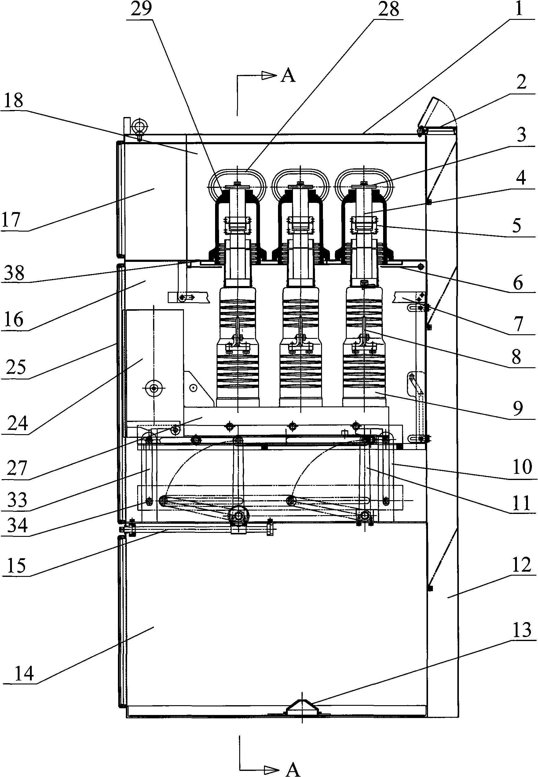
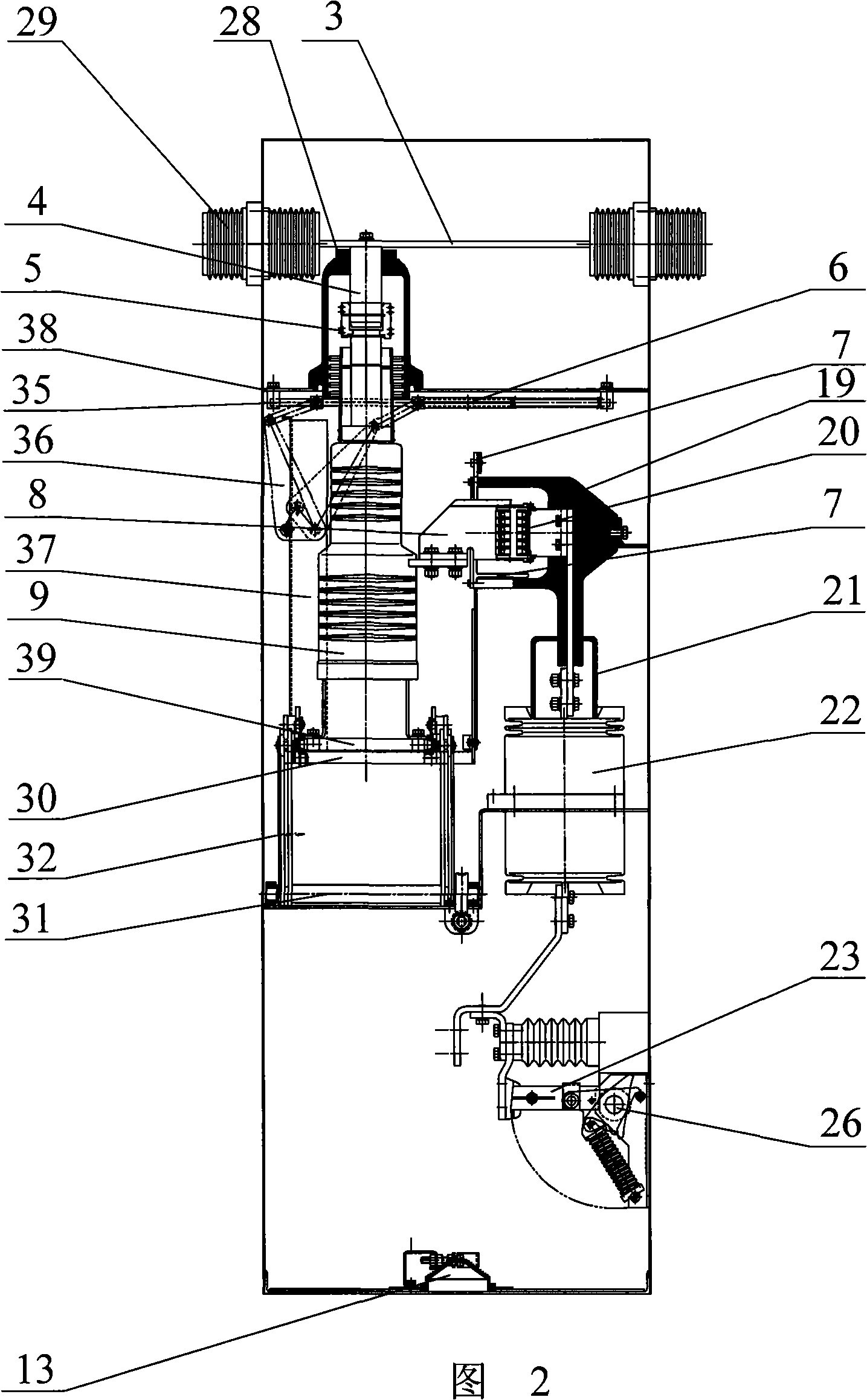
[0017] The present invention will be further described below in conjunction with specific drawings and embodiments.

[0018] As shown in the figure: a pressure relief chamber 12 is provided on the rear wall of the housing 1, a pressure relief chamber cover 2 is provided on the top of the pressure relief chamber 12, a relay instrument room 17 is provided on the upper part of the front wall of the housing 1, and the housing 1. The inner space of 1 is busbar chamber 18, circuit breaker chamber 16 and cable chamber 14 from top to bottom. In circuit breaker chamber 16, circuit breaker operating mechanism 24, circuit breaker chassis 27, circuit breaker three-phase pole 9 and For the circuit breaker handcart composed of the handcart chassis 39, the bottom surface of the cable chamber 14 is provided with a cable plug 13, and the middle part of each phase circuit breaker pole 9 is provided with a lower moving contact 8, and the circuit breaker chamber 16 is fixed with a The lower stati...


PUM


Abstract

The invention relates to a laterally-installed moving-type switch cabinet for receiving and distributing the electric energy, comprising a generatrix chamber, a breaker chamber, a relay meter chamber, a cable chamber and a voltage reliving chamber; the tri-phase polar pillar of the break is vertically distributed in the front and vertical direction of the switch cabinet; the moving direction of the hand cart is the vertical direction; the upper static contact head quietly through having touching the head box and fixing on generatrix bar directly of insulating sleeve function without the branch generatrix; the hand cart uses the electric or manual mechanism to move the hand cart entering the working position or the testing separating position; the breaker can process the electric opening and closing valve operation and the breaker processes the mechanical button operation via the emergency valve installed on the front plate, and the breaker can see the separating breaking opening of the main contact head via the observing window installed on the front plate.

Description


Claims


Application Information

Patent Timeline
Owner 高赟
Why Eureka
Try Eureka