Low-voltage high power multi-branch permanent magnet synchronous motor

A permanent magnet synchronous, high-power technology, applied in the direction of electric components, magnetic circuit rotating parts, electrical components, etc., can solve the problem of not solving the problem of high current, and achieve the effect of superior performance, cost reduction and energy saving effect.

Inactive Publication Date: 2008-12-10
ZHEJIANG YONGFA ELECTROMECHANICS LTD
View PDF3 Cites 6 Cited by
  • Summary
  • Abstract
  • Description
  • Claims
  • Application Information

AI Technical Summary

Problems solved by technology

However, the problem of high current under low voltage and high power conditions is still not solved

Method used


Image

  • Low-voltage high power multi-branch permanent magnet synchronous motor
  • Low-voltage high power multi-branch permanent magnet synchronous motor
  • Low-voltage high power multi-branch permanent magnet synchronous motor

Examples


Embodiment 1

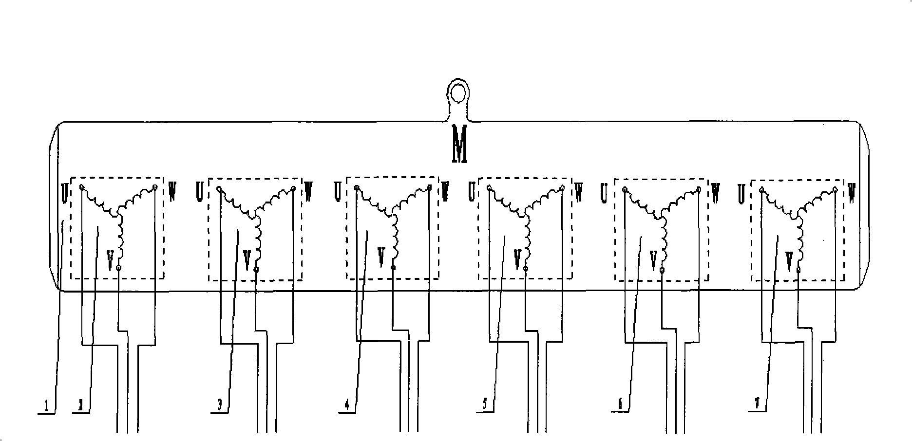
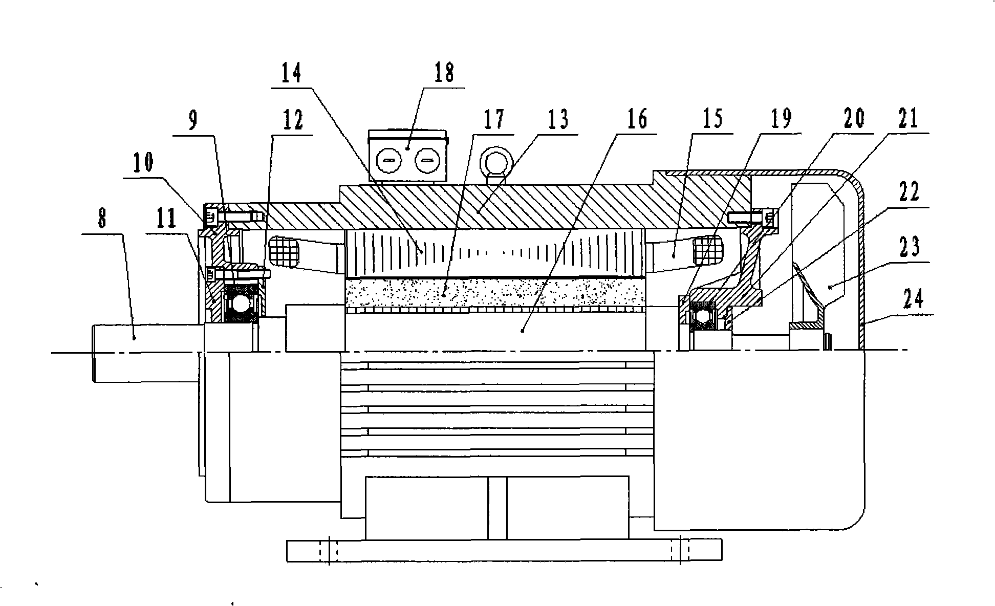
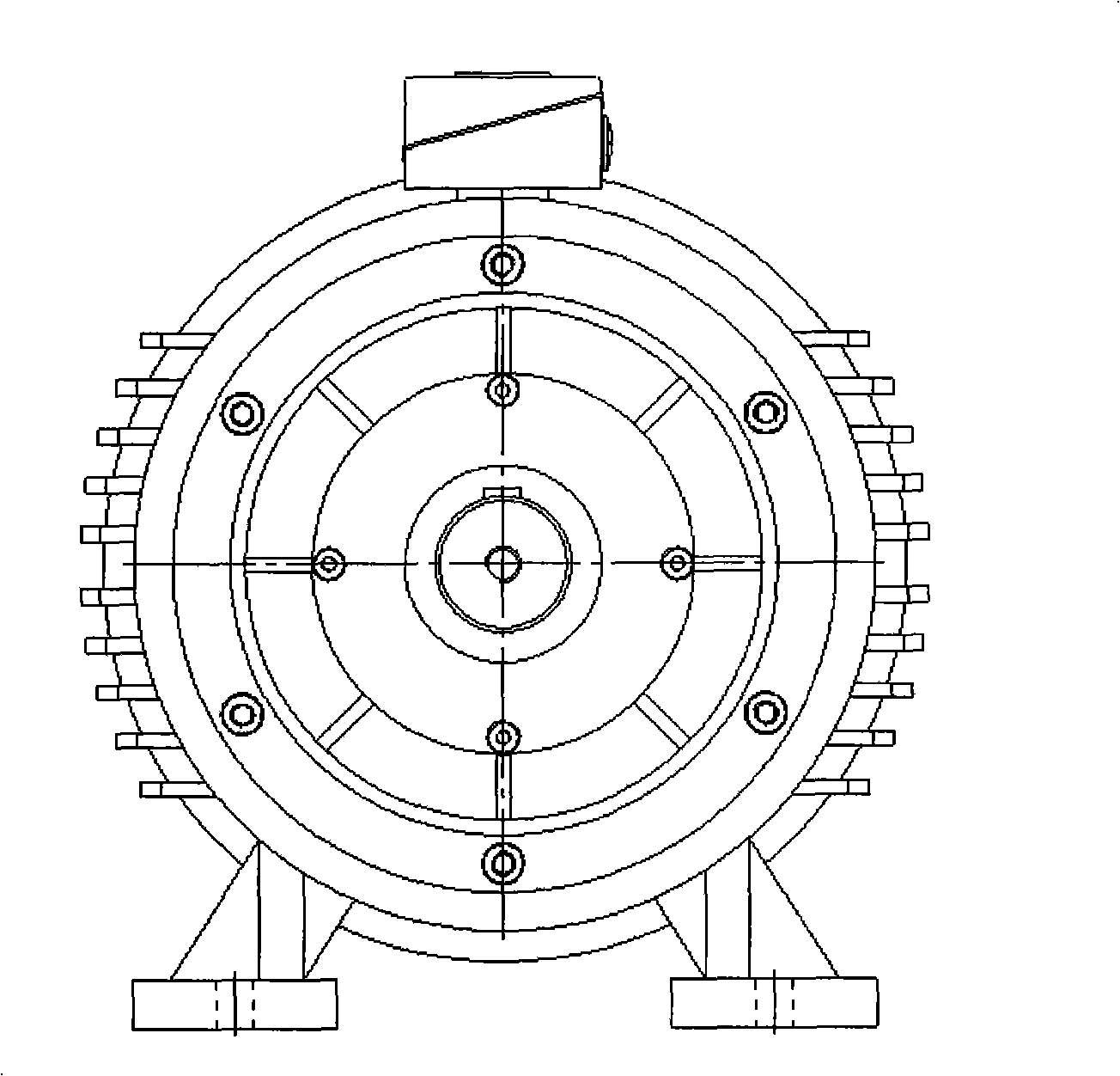
[0020] Embodiment 1 includes: permanent magnet synchronous motor housing 1, rotating shaft 8, left bearing 9, front end cover 10, left bearing outer cover 11, left bearing inner cover 12, machine base 13, stator core 14, stator winding 15, rotor 16 , permanent magnet 17, junction box 18, right bearing inner cover 19, right bearing 20, rear end cover 21, right bearing outer cover 22, fan 23, fan cover 24, junction box 18, bolt 18-1, terminal block 18- 2. Junction bucket 18-3, junction box seat 18-4. The left bearing outer cover 11 and the left bearing inner cover 12 are mounted on the front end cover 10 by bolts, the front end cover 10, the rear end cover 21 and the junction box 18 are respectively mounted on the machine base 13 with bolts, and the left bearing 9 is mounted on the rotor 16 Sandwiched between the left bearing outer cover 11 and the left bearing inner cover 12, the stator core 14 is directly mounted on the machine base 13 with bolts, the stator windings 15 are di...

Embodiment 2

[0021] The basic structure of the second embodiment is the same as that of the first embodiment, wherein the number of sub-winding groups is the same as the number of poles of the permanent magnet synchronous motor, and the rotor magnetic circuit structure is surface type.

Embodiment 3

[0022] The basic structure of the third embodiment is the same as that of the first embodiment, wherein the number of sub-winding groups is three times the number of poles of the permanent magnet synchronous motor, and the rotor magnetic circuit structure is a built-in type.


PUM


Abstract

A low voltage, high power and multi-branch permasyn motor belongs to the motor technical field; the motor includes a base, a stator winding, a rotor, a permanent magnet, a junction box and a fan; the stator winding is composed of a plurality of independent windings, which are distributed on the stator symmetrically; the three-phase terminals led out by each winding are connected with the terminals in the junction box arranged on the shell respectively, electrically connected with the terminal output ends of the junction box connected with each winding or respectively connected with each contactor respectively, or electrically connected with each frequency converter. The advantages of the motor are as follows: the problem of low cost performance of the corresponding high voltage frequency converter in the frequency converting, speed regulating and energy saving system is solved when the high voltage AC motor is taken as a main drive motor of the mechanical equipment; the control problem of the high-current contactor in the low voltage and high power AC motor is overcome; the problems such as current rating and difficult cooling are avoided when the low voltage and high power AC motor adopts a low voltage and high power frequency converter to supply power.

Description

technical field [0001] The invention belongs to the technical field of electric motors, and further relates to a low-voltage and high-power multi-branch permanent magnet synchronous motor, in particular to a main drive motor for large-scale mechanical equipment. Background technique [0002] In such industries as mining, electric power, metallurgy, petrochemical, cement, water supply and drainage and other industries, fans, pumps and mechanical equipment with large rotational inertia are usually driven by high-voltage asynchronous motors greater than 1kV. This voltage level not only brings many problems to the design, manufacture and maintenance of the motor, but more importantly, for the transmission system that requires variable speed and energy saving, the corresponding high-voltage inverter is very expensive and the cost performance is very low. The low-voltage high-power inverter often needs to be cooled by water cooling, and the current limit current value of the low-v...

Claims


Application Information

Patent Timeline
IPC IPC(8): H02K3/28H02K11/00H02K1/27H02K5/22
Inventor 张炳义冯桂宏刘宇
Owner ZHEJIANG YONGFA ELECTROMECHANICS LTD
Why Eureka
Try Eureka