Carbon fiber composite reinforced-core cable
A technology of composite reinforcing core and carbon fiber, applied in fiber processing, cables, insulated cables, etc., can solve problems such as poor compatibility and mismatch of thermal expansion coefficients
- Summary
- Abstract
- Description
- Claims
- Application Information
AI Technical Summary
Problems solved by technology
Method used
Image
Examples
Embodiment 1
[0041] The carbon fiber is T700 carbon fiber purchased from Japan Toray Company, and the glass fiber is continuous glass fiber yarn provided by China Glass Fiber. The resin composition contained 70% 331J bisphenol A epoxy resin from DOW Chemical Company and 30% Araldite 720 from Ciba Company, and the curing agent used diethylaminopropane (about 6% relative to the total resin composition).
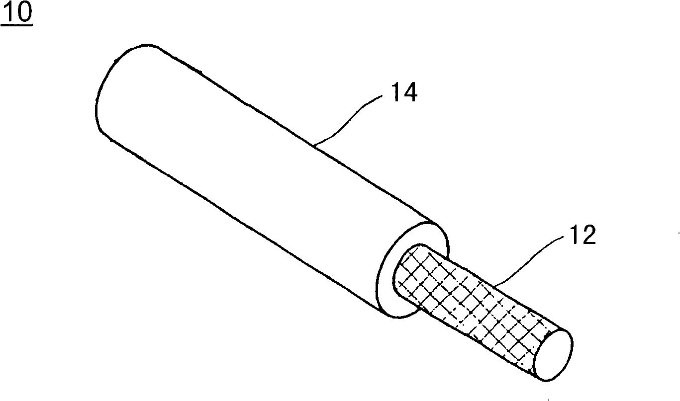
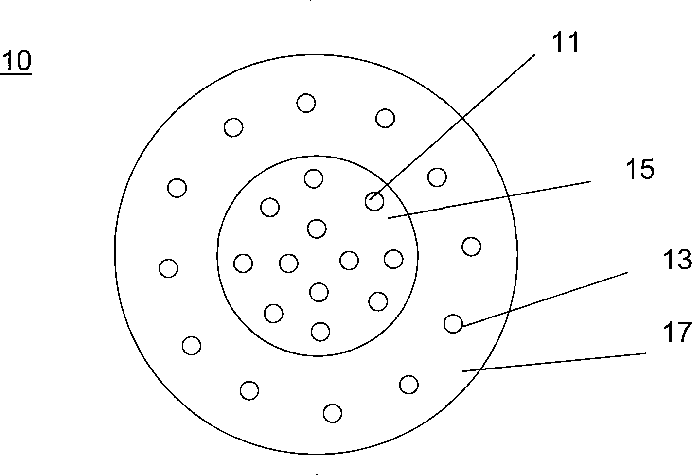
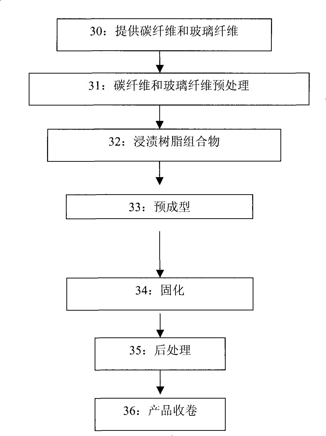
[0042] The above-mentioned raw materials are used to manufacture carbon fiber composite reinforced core cables using the aforementioned process. In the process, the preheating temperature is 80°C, the pre-curing temperature is 120°C, and the curing temperature is 180°C. The fiber volume ratio of the obtained composite reinforced core cable is 50%, the carbon fiber inner layer diameter is 4mm, the total diameter is 8mm, the tensile strength is 1540MPa, the elastic modulus is 165GPa, and the linear expansion coefficient is 1.9×10 -6 m / m / ℃.
[0043] The above-mentioned carbon fiber composite reinf...
Embodiment 2
[0045] The carbon fiber is T700 carbon fiber purchased from Japan Toray Company, and the glass fiber is continuous glass fiber yarn provided by China Glass Fiber. Araldite 720 from Ciba is used as the epoxy resin oligomer, and the curing agent is phthalic anhydride (about 15% relative to the total resin composition).
[0046] The above-mentioned raw materials are used to manufacture carbon fiber composite reinforced core cables using the aforementioned process. In the process, the preheating temperature is 80°C, the pre-curing temperature is 100°C, and the curing temperature is 150°C. The fiber volume ratio of the obtained composite reinforced core cable is 60%, the carbon fiber inner layer diameter is 5mm, the outer layer diameter is 7.75mm, the tensile strength is 2120MPa, the elastic modulus is 115GPa, and the linear expansion coefficient is 1.6×10 -6 m / m / ℃.
Embodiment 3
[0048] The carbon fiber composite reinforced core cable prepared in Example 2 is used to replace the steel core of the traditional aluminum conductor steel reinforced cable, that is, a double-layer trapezoidal aluminum strand is wound on the reinforced core cable prepared in Example 2. The cable has been tested by 3 kilometers of experimental lines, and it is confirmed that it can transmit 1000A current stably under 230kV without obvious cable sagging due to thermal effects. Compared with the aluminum conductor steel reinforced cable that transmits the same current, its weight is reduced by about 30%. In addition, the cable of the third embodiment can also stably transmit a larger current, which can reach 1200A. However, under such a large current, the traditional aluminum-conductor-steel-reinforced cable sags beyond the safety standard.
PUM
| Property | Measurement | Unit |
|---|---|---|
| Tensile strength | aaaaa | aaaaa |
| Tensile strength | aaaaa | aaaaa |
| Diameter | aaaaa | aaaaa |
Abstract
Description
Claims
Application Information
 - R&D
- Intellectual Property
- Life Sciences
- Materials
- Tech Scout
- Unparalleled Data Quality
- Higher Quality Content
- 60% Fewer Hallucinations
Browse by: Latest US Patents, China's latest patents, Technical Efficacy Thesaurus, Application Domain, Technology Topic, Popular Technical Reports.
© 2025 PatSnap. All rights reserved.Legal|Privacy policy|Modern Slavery Act Transparency Statement|Sitemap|About US| Contact US: help@patsnap.com


