Automobile permanent magnet generator with tiny output voltage ripple

A technology for permanent magnet generators and automobiles, applied to multi-output synchronous motors, control generators, electrical components, etc., can solve problems such as large output voltage ripples, achieve output ripple reduction, good low-speed power generation performance, and promote The effect of development

Inactive Publication Date: 2008-12-17
陈国弟
View PDF0 Cites 15 Cited by
  • Summary
  • Abstract
  • Description
  • Claims
  • Application Information

AI Technical Summary

Problems solved by technology

The automotive permanent magnet generator using this three-phase bridge controllable rectifier circuit is limited by volume and weight, and it is impossible to use a bulky reactor for smoothing and filtering. Therefore, there is a shortage of large output voltage ripples, which cannot be applied. For high-end cars with strict requirements on power quality

Method used


Image

  • Automobile permanent magnet generator with tiny output voltage ripple
  • Automobile permanent magnet generator with tiny output voltage ripple
  • Automobile permanent magnet generator with tiny output voltage ripple

Examples


Embodiment Construction

[0015] The technical invention will be further described below in conjunction with the accompanying drawings and embodiments.

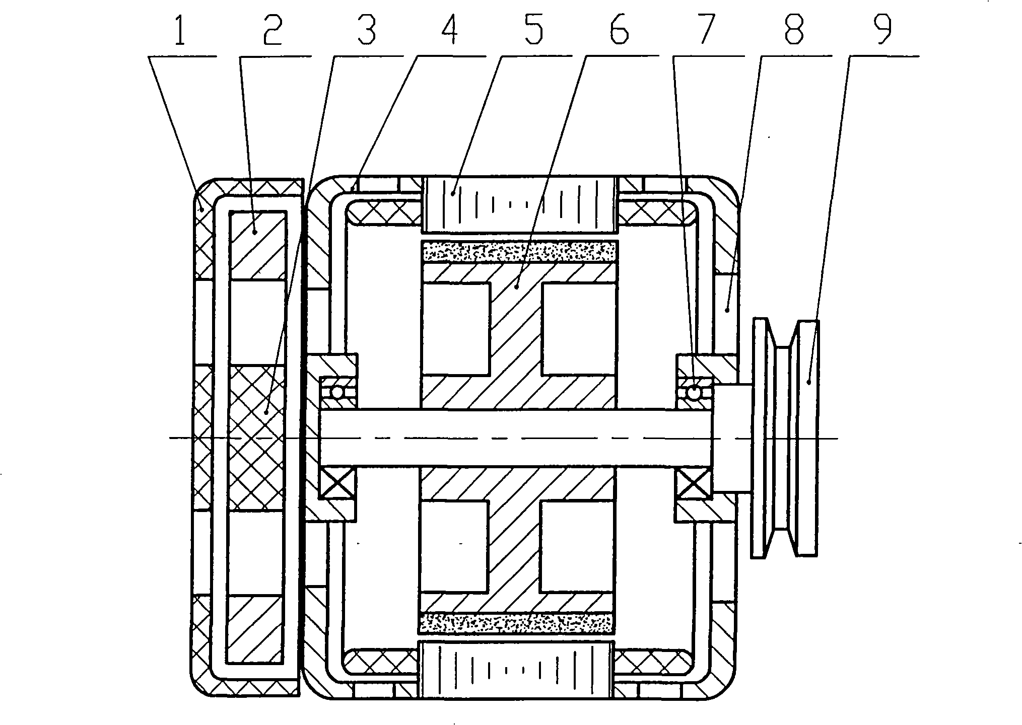
[0016] attached image 3 The automotive permanent magnet generator shown is mainly composed of a rear cover 1, a controllable rectifier 2, an electronic voltage regulator controller 3, a rear end cover 4, a stator 5, a permanent magnet rotor 6, a front cover 7, a bearing 8, and a pulley 9 When working, the belt pulley 9 drives the permanent magnet rotor 6 to rotate, and a three-phase AC voltage is induced on the winding of the stator 5. The controllable rectifier 2 adjusts the AC output of the stator 5 to a DC output, and the electronic voltage regulator controller 3 controls the controllable rectifier. The conduction angle of the thyristor on 2 makes the generator output a stable DC voltage.

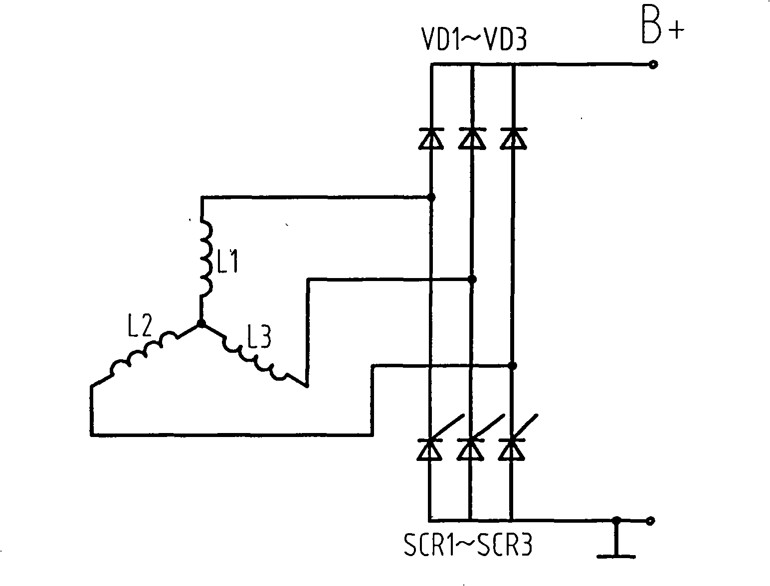
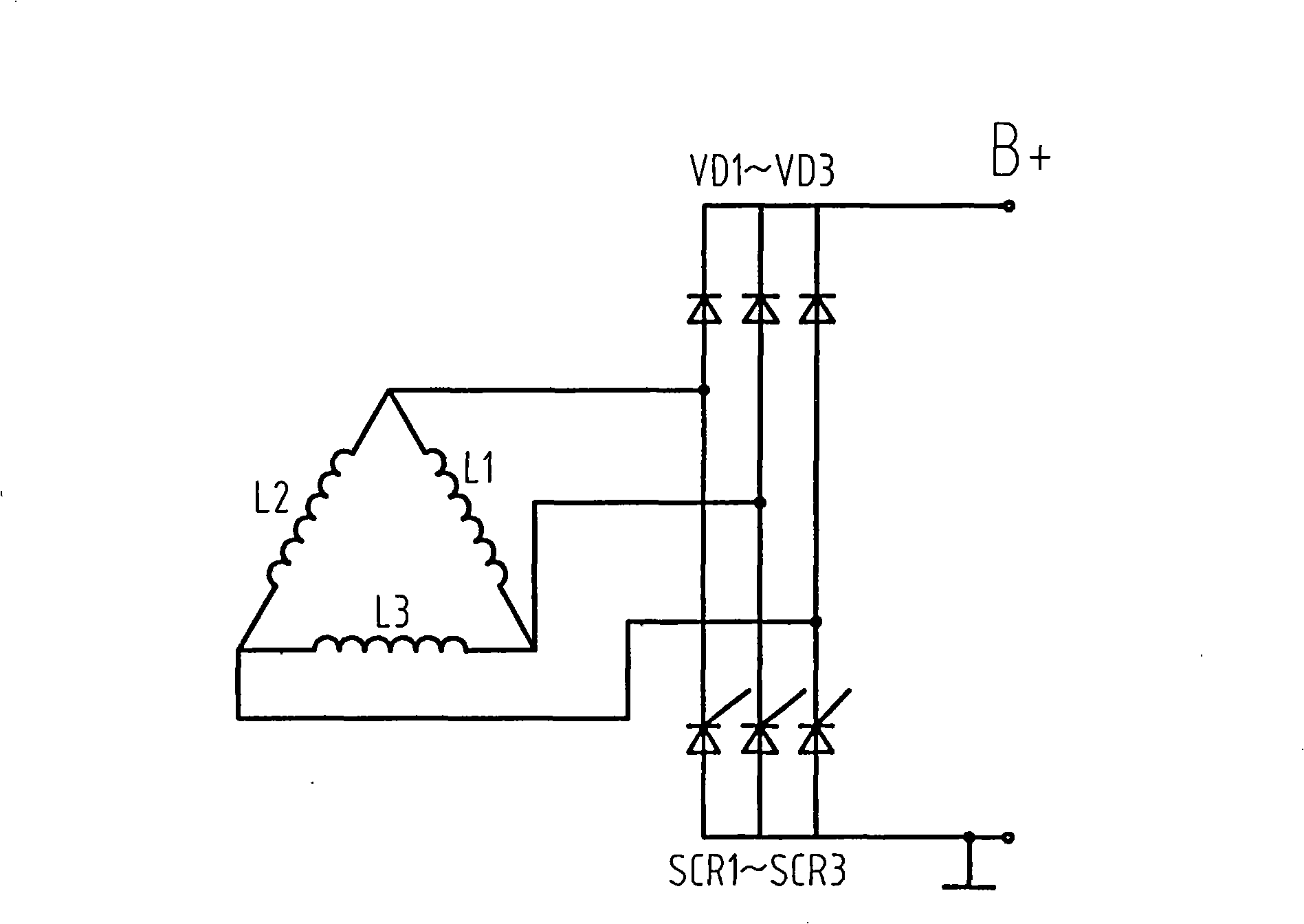
[0017] attached Figure 4 is attached image 3 The electrical schematic diagram of the rectification circuit of the automobile permanent magnet generator sh...


PUM


Abstract

A car permanent magnet generator is mainly composed of a rear cover, a three-phase bridge type controlled rectifier, an electronic voltage regulating controller, a rear end cover, a stator, a permanent magnet rotor, a bearing, a front end cover, a belt wheel, wherein the belt wheel drives the permanent magnet rotor to rotate, to cause the stator winding to induce out the three-phase alternating current, then is set as the DC output through the three-phase bridge type controlled rectifier. The electronic voltage regulating controller controls the angle of current flow of the thyristor, to cause the generator to output the stable DC voltage, characterized in that, the stator is arranged with two sets of three-phase windings, one is in the 'Y'-connection, and the other is in the 'triangle'-connection, which constitute two three-phase controlled bridge type rectifying circuits with the three-phase bridge type controlled rectifier, wherein the two rectifying circuits are in the parallel output. Due to the voltage phase difference 30 of the two windings, the output voltage pulses every 30 degrees, so the more the pulse times of the rectifying output voltage in a period is, the smaller the ripple of the output voltage of the car permanent magnet generator is.

Description

Technical field [0001] The technical invention relates to an automobile permanent magnet generator, which is especially suitable for high-end automobiles with strict requirements on power supply quality. Background technique [0002] Since the rotor magnetic field of the automobile permanent magnet generator is not adjustable, it is generally used as attached figure 1 or attached figure 2 The shown three-phase controllable bridge rectifier circuit regulates the output of the generator so that the generator outputs a stable DC voltage. The automotive permanent magnet generator using this three-phase bridge controllable rectifier circuit is limited by volume and weight, and it is impossible to use a bulky reactor for smoothing and filtering. Therefore, there is a shortage of large output voltage ripples, which cannot be applied. For high-end cars that have strict requirements on power quality. Contents of the invention [0003] The purpose of the technical invention is t...

Claims


Application Information

Patent Timeline
Patent Type & Authority Applications(China)
IPC IPC(8): H02K21/48H02P9/48
Inventor 陈国弟
Owner 陈国弟
Why Eureka
Try Eureka