Power control method and apparatus for adjusting light of gas discharging light source

A gas discharge and power control technology, applied in the field of gas discharge light source dimming power control, can solve the problems of high manufacturing process, expensive production cost, and inability to adjust brightness, and achieve the effect of simple circuit, low manufacturing cost and high reliability

Inactive Publication Date: 2012-06-27
陈自拯
View PDF0 Cites 0 Cited by
  • Summary
  • Abstract
  • Description
  • Claims
  • Application Information

AI Technical Summary

Problems solved by technology

[0002] At present, all electronic energy-saving lamps cannot be adjusted in brightness like incandescent lamps. If dimming is to be achieved, a dedicated chip must be used to achieve dimming function like the electronic ballast of fluorescent lamps. That is to say, most dimmable gas Discharge light sources all use ASICs to realize the dimming function, but this dimming method, the circuit is very complicated, requires high manufacturing technology and expensive production costs, it is difficult to realize it in electronic energy-saving lamps, and thus Difficult to popularize in the lighting market

Method used


Image

  • Power control method and apparatus for adjusting light of gas discharging light source
  • Power control method and apparatus for adjusting light of gas discharging light source

Examples


Embodiment 1

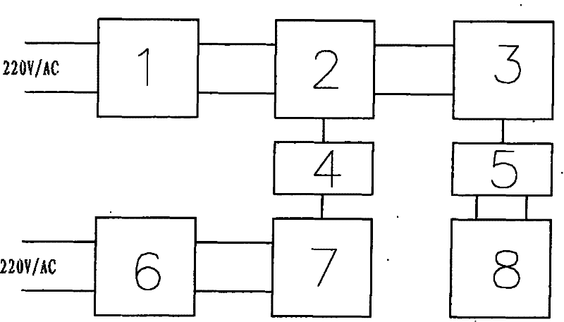
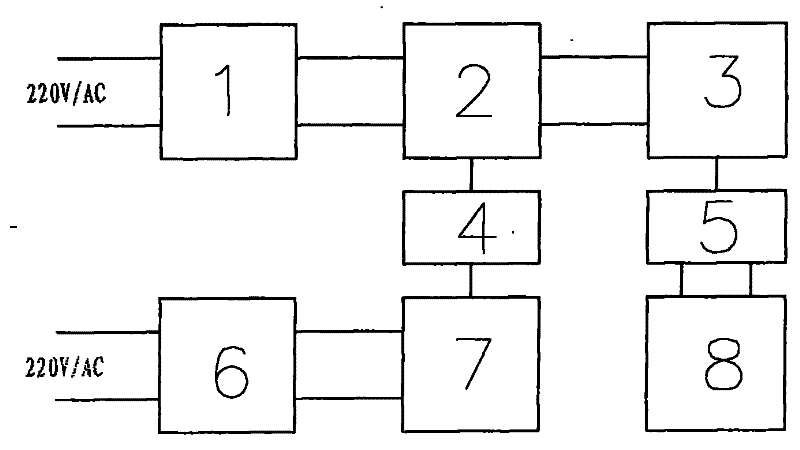
[0013] Such as figure 1 As shown, the dimming power control method of a gas discharge light source described in this embodiment is to use electromagnetic force to act on the controllable components of the oscillating circuit, so that the operating frequency of the driver of the electronic energy-saving lamp is controlled by the change of the superimposed electromagnetic field, and the voltage -Frequency conversion to achieve 100% to zero output power control of electronic energy-saving lamps by adjusting an input voltage varying from zero to 10 volts.

[0014] The gas discharge light source dimming power control device designed in the present invention includes a rectification filter circuit 1, a self-excited oscillation circuit 2, a PPFC circuit 3 and a resonant circuit 5, and the output of the resonant circuit 5 is connected to the gas discharge light source 8. The oscillating circuit 2 is connected with a coupling drive unit 4 , the input end of the coupling drive unit 4 is...


PUM


Abstract

The invention discloses a gas discharge lamp dimming power control method and a device, which adopts a controllable element of which an electromagnetic force acts on an oscillation circuit so that the working frequency of a driver of an electronic energy-saving lamp is controlled by the change of a stacked electromagnetic field to realize the conversion between voltage and frequency and realizes a hundred percent to zero of output power control of the electronic energy-saving lamp via adjusting an input voltage which changes in the range of 0 volt to 10 volts. The device consists of a rectifier and filter circuit, a self-excited oscillating circuit, a PPFC circuit and a resonant circuit, wherein the output of the resonant circuit is connected with a gas discharge lamp, a coupling driving unit is connected on the self-excited oscillating circuit, an electromagnetic frequency modulation control circuit is connected with an input end of the coupling driving unit, and an adjustable directcurrent supply in the range of 0 volt to 10 volts is connected with an input end of the electromagnetic frequency modulation control circuit. When implemented, the invention only adds dimming controlinto the original circuit without needing to redesign a new circuit so that a dimming circuit doesn't influence the parameters of the main circuit and the original technical parameters of the electronic energy-saving lamp also basically need not to be changed. The invention has the advantages of simple circuit, no need of complex manufacturing technology, high reliability, low manufacturing cost,etc.

Description

technical field [0001] The invention relates to an energy-saving lighting technology, in particular to a method and device for controlling the dimming power of a gas discharge light source. Background technique [0002] At present, all electronic energy-saving lamps cannot be adjusted in brightness like incandescent lamps. If dimming is to be achieved, a dedicated chip must be used to achieve dimming function like the electronic ballast of fluorescent lamps. That is to say, most dimmable gas Discharge light sources all use ASICs to realize the dimming function, but this dimming method, the circuit is very complicated, requires high manufacturing technology and expensive production costs, it is difficult to realize it in electronic energy-saving lamps, and thus It is difficult to popularize and promote in the lighting market. Contents of the invention [0003] The object of the present invention is to provide a gas discharge light source dimming power control method and de...

Claims


Application Information

Patent Timeline
Patent Type & Authority Patents(China)
IPC IPC(8): H05B41/38
Inventor 徐杰陈自拯俞广祥陈波
Owner 陈自拯
Why Eureka
Try Eureka