
Anti-scatter grid for an x-ray device with non-uniform distance and/or width of the lamellae

An anti-scatter, grid technology used in materials analysis using radiation, radiation/particle processing, using apertures/collimators, etc.

Inactive Publication Date: 2008-12-17
KONINKLIJKE PHILIPS ELECTRONICS NV
View PDF1 Cites 13 Cited by
  • Summary
  • Abstract
  • Description
  • Claims
  • Application Information

AI Technical Summary

Problems solved by technology

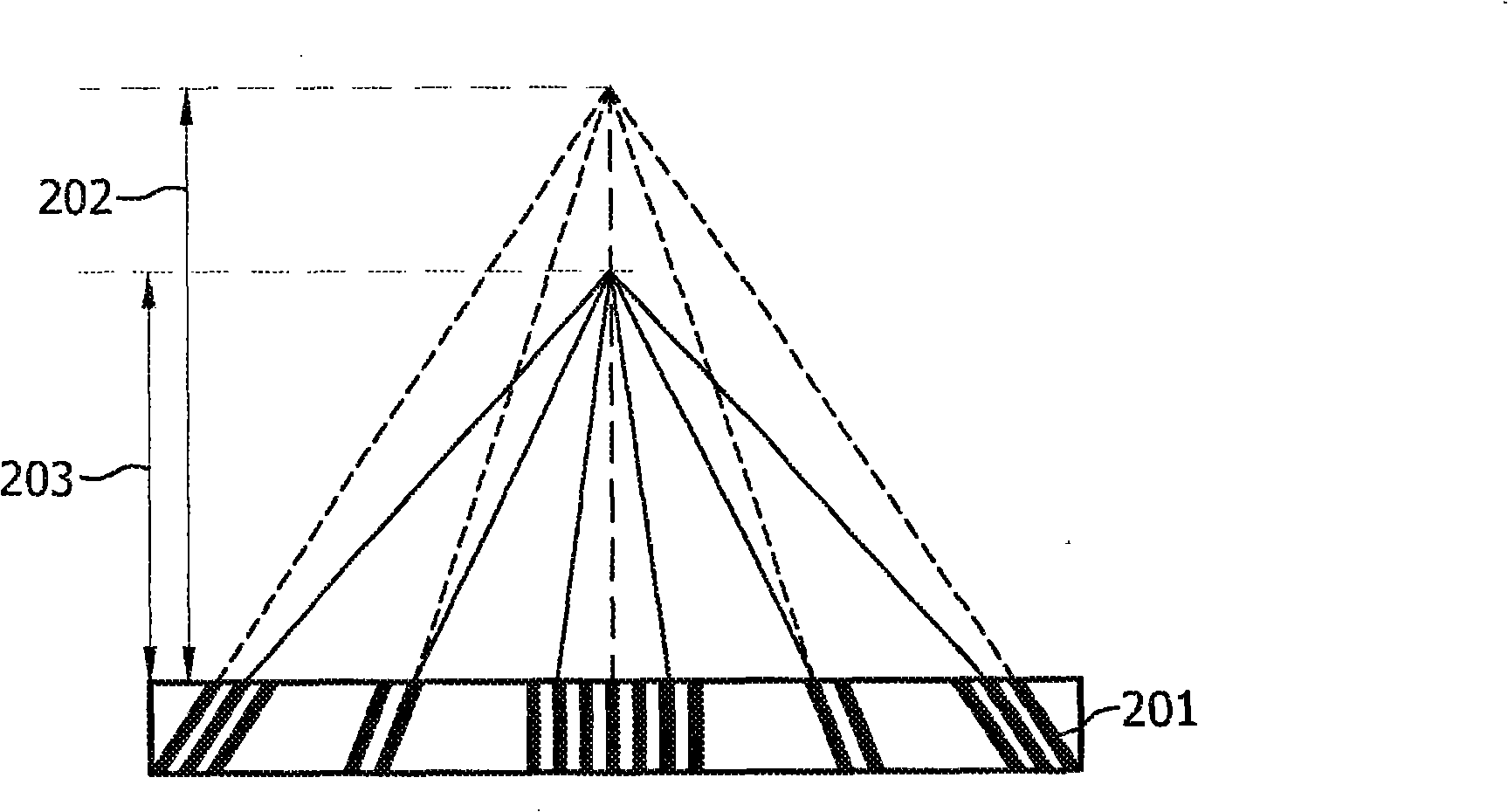
However, in clinical practice the distance between source and detector (SID) is often variable relative to the standard SID (=grid focal distance), when the SID is not equal to the grid focal distance, in the grid Increased attenuation occurs in the primary radiation at the edges, although grid performance is not adversely affected around the grid center

Method used


Image

  • Anti-scatter grid for an x-ray device with non-uniform distance and/or width of the lamellae
  • Anti-scatter grid for an x-ray device with non-uniform distance and/or width of the lamellae
  • Anti-scatter grid for an x-ray device with non-uniform distance and/or width of the lamellae

Examples


Embodiment Construction

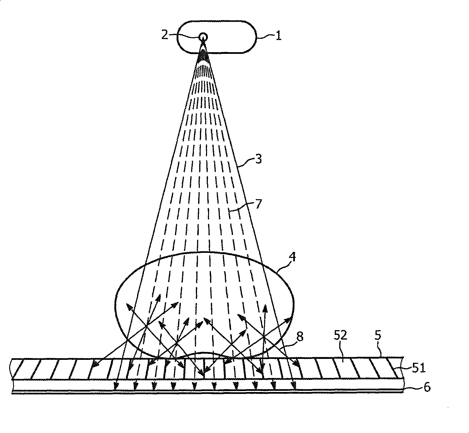
[0019] image 3 is a sketch of an x-ray system with an anti-scatter grid. From a focal point 2 of an X-ray tube 1 an X-ray beam 3 is applied to an object 4 to be examined, eg a patient. The X-rays penetrating the object 4 to be inspected then impinge on the anti-scatter grid 5 and the remaining radiation fraction finally impinges on the X-ray detector 6 . The anti-scatter grid 5 mainly includes: an absorbing layer or flakes 51; and a trench medium or filling material 52 provided between the flakes. The flakes are usually made of lead with a high absorption of X-rays and have a small volume and are oriented towards the grid focus at a distance from the grid 5, which in this case corresponds to the focus 2 . The trenched media 52 often comprises fiber, paper or aluminum and maximizes the transmission of x-rays.

[0020] The anti-scatter grid 5 is mainly used to pass the primary radiation 7 which penetrates the object 4 to be inspected, so that this radiation can impinge on t...


PUM


Abstract

An anti-scatter grid (5) for an X-ray device, comprising a plurality of lead lamellae (51) focussed downward and a fixed grid- focus distance (202) and having a filler material (52) therebetween. The width of the lamellae (51) at the edges of the grid (5) is less than that at the centre of the grid (5), and / or the width of the filler material portions (52) is greater at the edges than at the centre of the grid (5). Thus, when the source-to-image distance (SID, 203) varies relative to the grid-focus distance (202), the transmission of the primary radiation beam at the edges of the grid (5) is not adversely affected.

Description

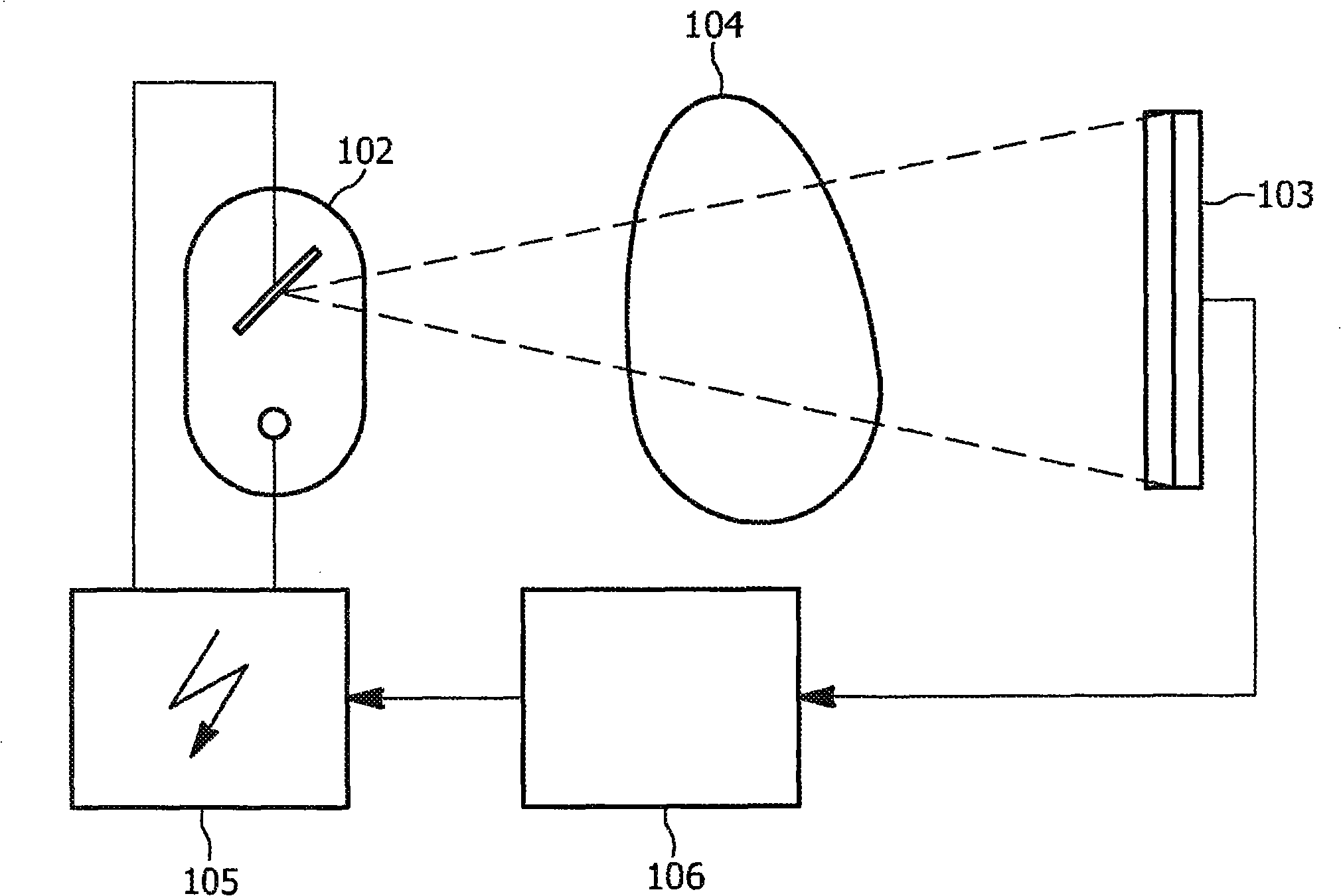
technical field [0001] The invention relates to an anti-scatter grid for use in an X-ray apparatus for reducing scatter within an X-ray image. Background technique [0002] It is well known in the field of non-invasive medical diagnosis to obtain a radiation image of an object to be examined by irradiating it with X-radiation and detecting the intensity distribution of the radiation transmitted through the object. [0003] Refer to the attached figure 1 , which schematically exemplifies a typical X-ray system, which includes an X-ray image detection sensor unit 103, which includes a plurality of photoelectric conversion elements. An X-ray source 102 supplied by a high-voltage generator 105 generates X-rays transmitted through a target 104 to a sensor unit 103 . The photoelectric conversion elements of the sensor unit 103 generate an image signal representing the intensity distribution of the radiation transmitted through the object 104 . The image data is provided to a di...

Claims


Application Information

Patent Timeline
Patent Type & Authority Applications(China)
IPC IPC(8): G21K1/02G21K3/00G01N23/06
CPCG01N23/04G21K1/025
Inventor J·C·W·范弗罗恩霍芬
Owner KONINKLIJKE PHILIPS ELECTRONICS NV
Learn More