Thrust generator for a propulsion system

A thrust generator, generator technology, applied in the direction of high-efficiency propulsion technology, engine control, power plant type, etc., can solve problems such as engine damage

Inactive Publication Date: 2008-12-24
GENERAL ELECTRIC CO
View PDF3 Cites 17 Cited by
  • Summary
  • Abstract
  • Description
  • Claims
  • Application Information

AI Technical Summary

Problems solved by technology

Due to practical limitations on parameters such as engine nacelle size and fan size, these devices have limited propulsion efficiency and are prone to engine damage due to foreign object debris (FOD)

Method used


Image

  • Thrust generator for a propulsion system
  • Thrust generator for a propulsion system
  • Thrust generator for a propulsion system

Examples


Embodiment Construction

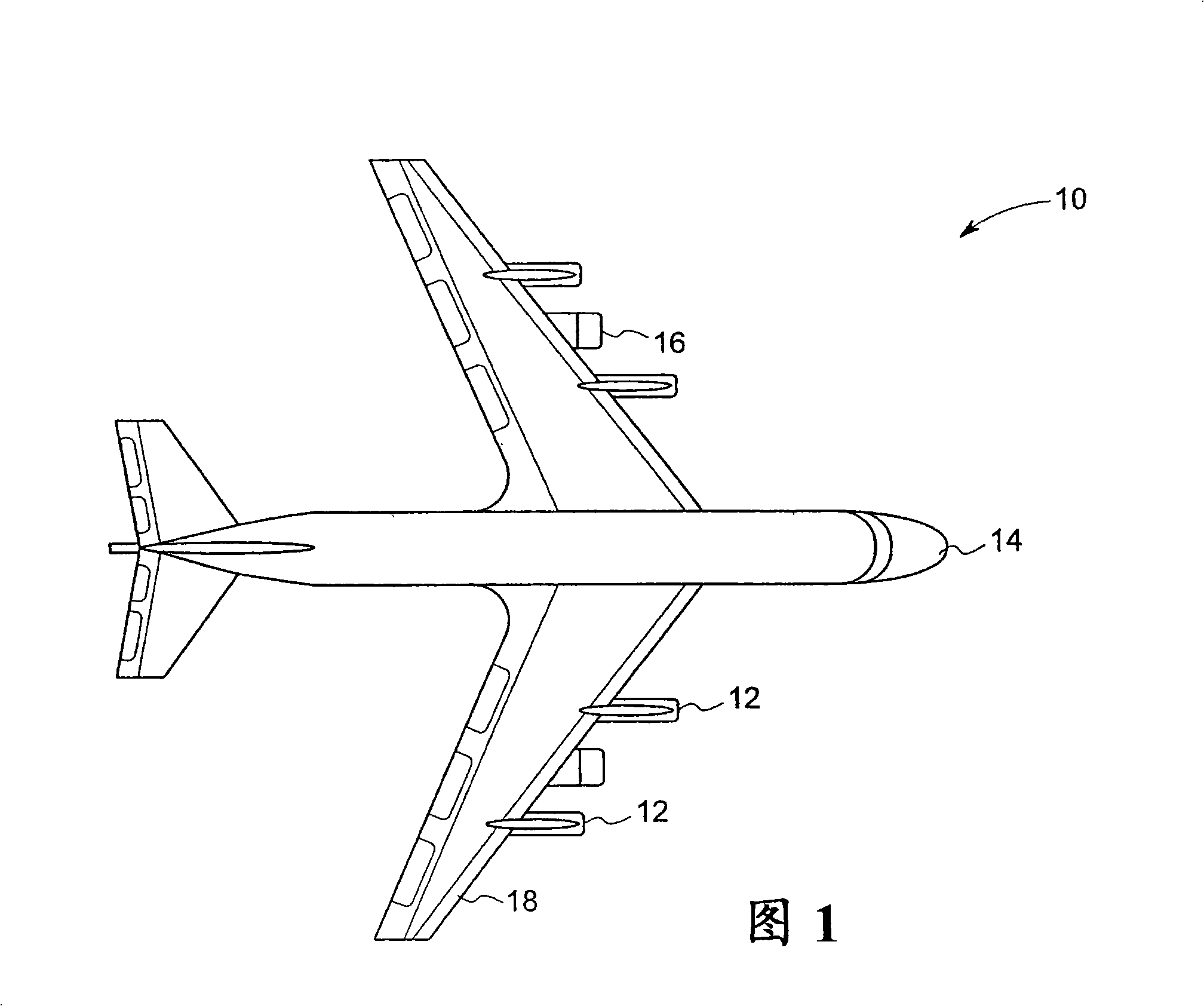
[0072]As discussed in more detail below, embodiments of the present technology function to increase the efficiency of propulsion systems, such as jet aircraft powered by turbojet engines. Specifically, the present technology utilizes a combination of working fluid and ambient air to generate thrust to drive a propulsion system, thereby increasing the efficiency of the system and reducing specific fuel consumption. Turning now to the drawings and referring initially to FIG. 1 , there is shown an aircraft 10 having a plurality of thrust generators, indicated generally at 12 . Aircraft 10 includes an aircraft frame 14 and a gas generator 16 coupled to the aircraft frame 14 . In the exemplary embodiment, gas generator 16 includes a jet engine configured to generate exhaust. As shown, aircraft 10 includes two jet engines 16 located at wings 18 of the aircraft. However, more or fewer gas generators or jet engines 16 may be utilized to power aircraft 10 and generate exhaust.

[00...


PUM


Abstract

A thrust generator for thrust system is provided. The thrust generator includes an air inlet configured to introduce air within the thrust generator and a plenum configured to receive exhaust gas from a gas generator and to provide the exhaust gas over a Coanda profile, wherein the Coanda profile is configured to facilitate attachment of the exhaust gas to the profile to form a boundary layer and to entrain incoming air from the air inlet to generate thrust.

Description

technical field [0001] The present invention relates generally to propulsion systems, and more particularly, to thrust generators for improving the efficiency of propulsion systems. Background technique [0002] Various propulsion systems are known and used. For example, in a jet aircraft powered by a turbojet engine, air enters the inlet and is then compressed to a higher pressure by a rotary compressor. The compressed air is passed to the combustion chamber where it is mixed with fuel and ignited. The hot combustion gases then enter a turbine where power is extracted to drive the compressor. In a turbojet, exhaust gas from a turbine is accelerated through a nozzle to provide thrust. [0003] In addition, the exhaust flow is expanded to atmospheric pressure through a propelling nozzle, which produces a net thrust to propel the jet vehicle. Typically, in a turbojet engine, the thrust nozzle is close to choke. Since the only way to increase thrust is to increase the ther...

Claims


Application Information

Patent Timeline
Patent Type & Authority Applications(China)
IPC IPC(8): B64D27/16
CPCB64D27/02B64D27/16F02K7/08F02K7/12F05D2270/173Y02T50/60
Inventor A·T·埃武莱特L·C·哈伯
Owner GENERAL ELECTRIC CO
Why Eureka
Try Eureka