Softener box fully dissolving and emptying softener and working method thereof
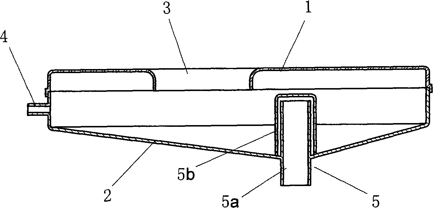
A technology of fully dissolving and softening agent, applied in the field of softener box that fully dissolves and empties the softener, can solve the problems of residue, inability to add, affect the softening effect of clothes, etc., and achieve the effect of simple structure
- Summary
- Abstract
- Description
- Claims
- Application Information
AI Technical Summary
Problems solved by technology
Method used
Image
Examples
Embodiment 1
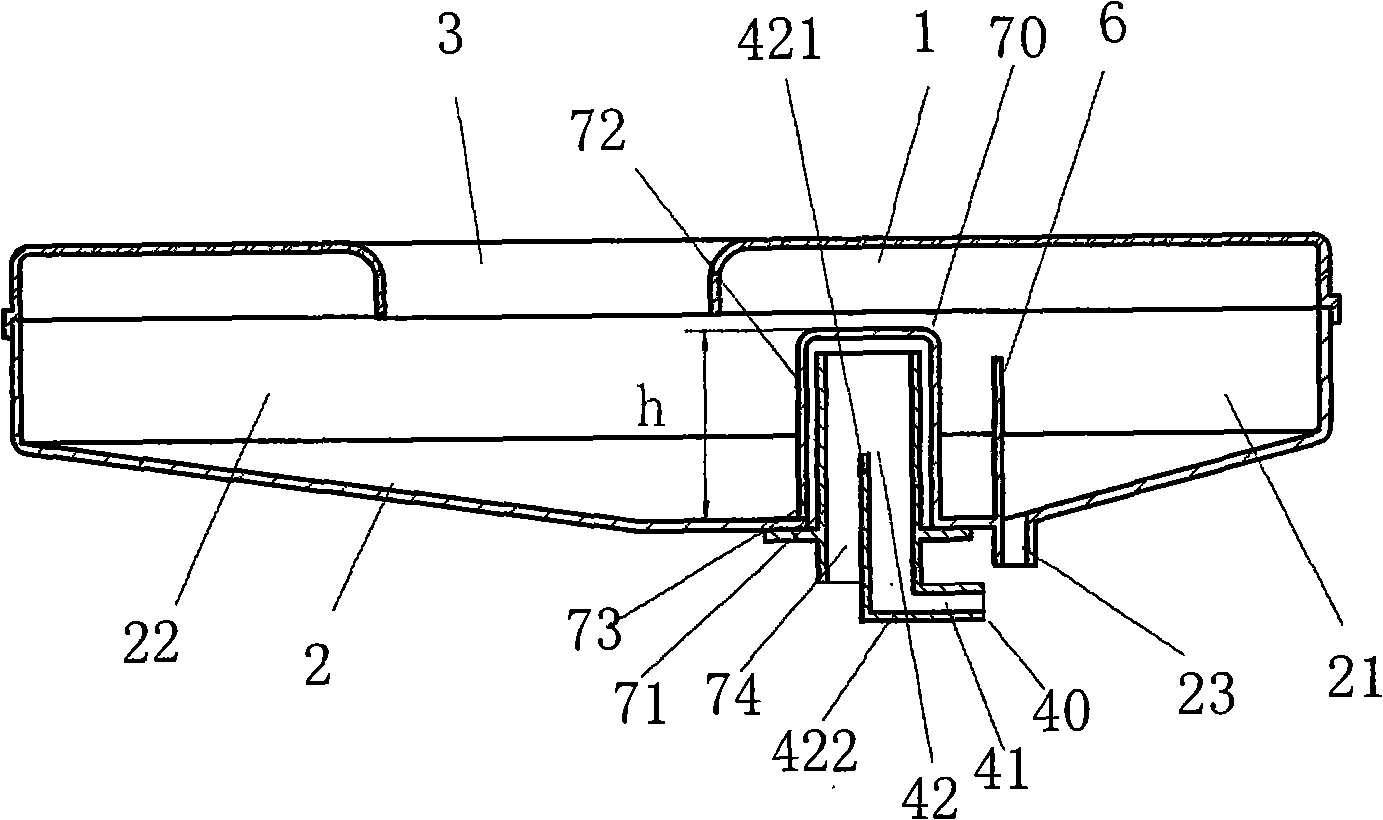
[0028] figure 2 It is a structural schematic diagram of Embodiment 1 of the softener box of the present invention. The present invention provides a softener box that is simple in structure and can be fully and cleanly discharged, including: a box cover 1, a box body 2, a water inlet pipe, and a siphon drain pipe 70 arranged at the bottom of the box body, and the water inlet pipe 40 is integrated. In the discharge pipe 71, its water outlet is towards the top of the siphon discharge pipe.
[0029] The siphon drain pipe 70 is composed of a drain pipe 71 and a siphon cap 72 buckled on the drain pipe 71. The drain pipe 71 passes through the bottom of the box body and is sealed and fixed with the bottom of the box body. One end protrudes from the bottom of the softener box body 1. The siphon cap 72 fastened on the drain pipe is a round pipe with a diameter slightly larger than the outer diameter of the drain pipe. A siphon opening 73 is provided between the bottom surfaces of the...
Embodiment 2
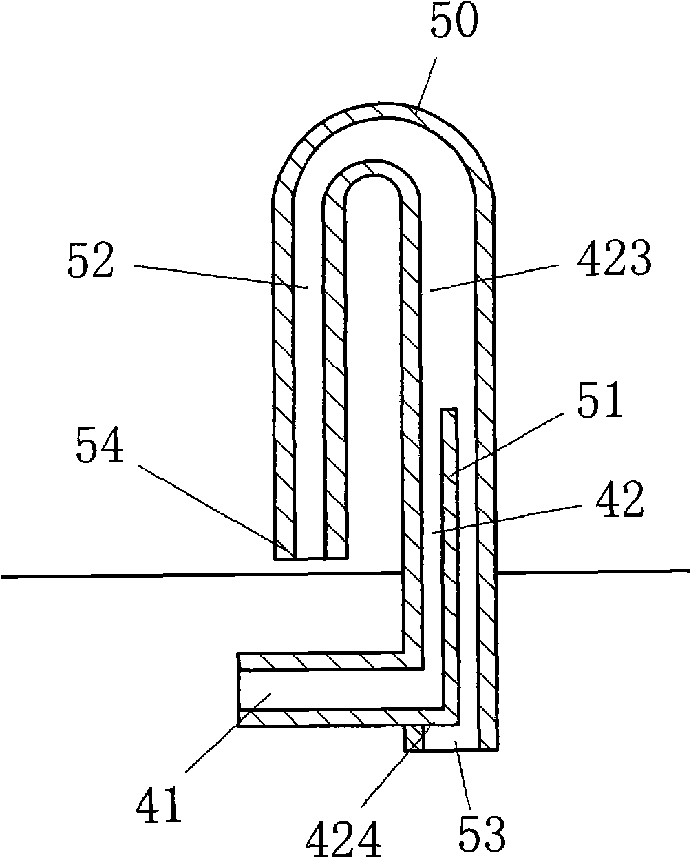
[0036] image 3 It is a structural schematic diagram of another water inlet pipe of the present invention. In this embodiment, the siphon discharge pipe is an inverted U-shaped tube 50, the inverted U-shaped tube 50 is composed of two tubes with different diameters, the large-diameter tube 51 of the inverted U-shaped tube is connected to the The bottom of the box body is integrally formed and stretches out from the bottom of the box body to form a softener discharge port 53, and the small-diameter tube 52 of the U-shaped pipe leaves a certain gap with the bottom of the box body to form a softener siphon port 54.
[0037] The water inlet pipe 40 that is located in the siphon discharge pipe is also an L-shaped pipe formed by a horizontal pipe 41 and a vertical pipe 42, and the vertical pipe is arranged in the large-diameter pipe 51; The diameter pipe 51 protrudes from the side of the other end (i.e. softener outlet 53) at the bottom of the box body.
[0038] The vertical pipe 42...
Embodiment 3
[0040] Figure 4 It is another structural schematic diagram of the water inlet pipe of the present invention. Figure 4 In the shown embodiment, the siphon discharge pipe 60 is a round pipe 62 with a head 61 at the upper end, and a partition 63 is arranged inside the round pipe 62, and the partition 63 separates the round pipe 62 into a top-connected section. Two semi-circular tubes 65, 64 of different sizes, wherein: the nozzle of the large semi-circular tube 65 stretches out from the bottom of the softener box body to form a softener outlet 66, and the nozzle of the small semi-circular tube 64 is located at the bottom of the softener box body and is the lowest position, forming a siphon mouth 67; the water inlet pipe located in the siphon drain pipe is formed by being located at the horizontal pipe 41 on the large semicircular pipe 65 at the bottom of the softener box box body and being located at the pair in the large semicircular pipe 65 The vertical baffle plate 425 and ...
PUM
 Abstract
Description
Claims
Application Information
 - R&D
- Intellectual Property
- Life Sciences
- Materials
- Tech Scout
- Unparalleled Data Quality
- Higher Quality Content
- 60% Fewer Hallucinations
Browse by: Latest US Patents, China's latest patents, Technical Efficacy Thesaurus, Application Domain, Technology Topic, Popular Technical Reports.
© 2025 PatSnap. All rights reserved.Legal|Privacy policy|Modern Slavery Act Transparency Statement|Sitemap|About US| Contact US: help@patsnap.com


