Split solar water heater

A solar water heater, solar heat collection technology, applied in the directions of solar heat collectors, solar thermal energy, solar heat collectors using working fluids, etc., can solve the problems of inability to use, difficult for households to use, inflexible installation, etc., and achieve low cost Efficient heat exchange, strong water supply power, flexible and convenient installation

Inactive Publication Date: 2008-12-24
A O SMITH CHINA WATER HEATER CO LTD
View PDF1 Cites 5 Cited by
  • Summary
  • Abstract
  • Description
  • Claims
  • Application Information

AI Technical Summary

Problems solved by technology

However, the water tank of this kind of water heater is directly connected to the vacuum heat collecting pipe through the heat pipe, so it must be installed together, and the separation of heat collection and hot water supply cannot be realized. Not only is the installation not flexible enough, but also it is inconvenient to popularize and apply.
For example, it is difficult for the downstairs residents with less sunshine hours to use; for example, the bathrooms of the houses facing north cannot be used.
Therefore, it has not been practically applied so far

Method used


Image

  • Split solar water heater

Examples


Embodiment 1

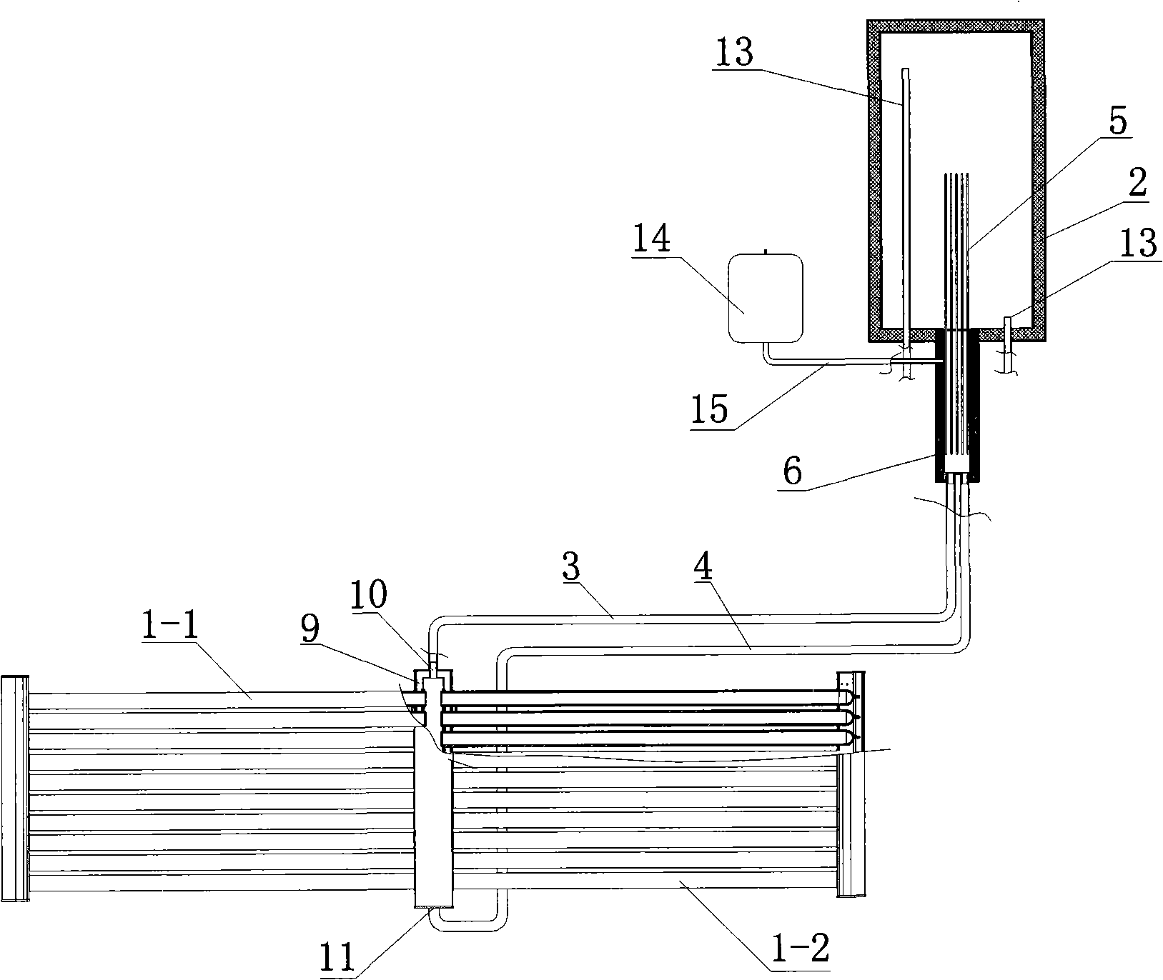
[0011] The split solar water heater of this embodiment is such as figure 1 As shown, it includes two sets of vacuum tubes 1-1, 1-2 arranged outdoors, a pressurized water tank 2 arranged indoors, an outlet connecting pipe 3 passing through the indoor and outdoor, an inlet connecting pipe 4 and twelve heat pipes 5. A connecting box 9 is provided between the two sets of horizontal vacuum tubes 1-1 and 1-2. The connecting box 9 connects the two sets of vacuum tubes 1-1 and 1-2 to form a fish-ridge-shaped solar heat collector, which is very suitable for installation on the balcony. One side. The upper and lower ends of the connection box 9 are respectively provided with an upper outlet 10 and a lower inlet 11. The heat exchange box 6 is installed on the outer wall of the bottom of the pressurized water tank 2, and an inlet 7 and an outlet 8 are opened at the bottom of the heat exchange box 6. One ends of the outlet connecting pipe 3 and the inlet connecting pipe 4 are respectively conn...

Embodiment 2

[0021] The basic structure of the split-type solar water heater in this embodiment is the same as that of the first embodiment. The difference is that the capillary action uses a non-gravity heat pipe, so the heat exchange box can be placed on the side of the water tank, and the heat pipe is in a horizontal state; The position is lower than the solar heat collection device, because an infusion pump is added to the circulation loop, which can also achieve the required heat exchange cycle; in addition, the water tank is an electric water heater tank with an electric heating rod installed therein, so the solar heating in this embodiment It forms a complementary heating system with electric heating.


PUM


Abstract

The invention relates to a split solar energy water heater, belonging to the solar energy water heating technical field and comprising a pressure-bearing water tank, a heat tube and a solar energy heat collecting device, a heat exchanging tank and an in-out connecting tube in which an anti-freezing heat-exchanging medium is respectively filled; wherein, an inlet and an outlet of the solar energy heat collecting device are respectively communicated with the heat-exchanging tank through the in-out connecting tube to form a circulation loop. An upper radiation section of the heat tube is positioned in the pressure-bearing water tank and a lower heat absorbing section is positioned in the heat exchanging tank. The invention realizes the heat transmission between the solar energy heat collecting device and the pressure-bearing water tank which is provided with strong water transmission power to meet the requirement of users well; the heat collecting device, the heat exchanging tank and the in-out connecting tube are not directly communicated with the pressure-bearing tank so as to fill the anti-freezing heat-exchanging medium and to lead the external parts to obtain the required anti-freezing effect; the organic combination between the circulation loop and a second-level heat exchanging of the heat tube just needs a less quantity of heat tube, so as to realize both the high-effective heat exchanging and the distinct manufacturing-cost reduction.

Description

Technical field [0001] The invention relates to a solar water heater, in particular to a pressure-bearing solar water heater, belonging to the technical field of water heaters. Background technique [0002] Traditional solar water heaters are usually direct heat exchange systems with an integrated structure composed of a vacuum heat collection tube and a non-pressurized water tank directly connected. This traditional solar water heater has high heat exchange efficiency, but its shortcomings are also obvious: it is large in size and must be placed outdoors, not only inconvenient to install, but also limited in use by multiple households on the first floor; and the water tank is in a non-pressurized state and the water supply power is insufficient. [0003] In order to overcome the problem of insufficient power for non-pressurized water supply, the Chinese patent application with application number 01103950.7 and titled "New Generation Metal Glass Vacuum Tube Solar Water Heater" di...

Claims


Application Information

Patent Timeline
IPC IPC(8): F24J2/00F24J2/04F24J2/32F24J2/05F24J2/46F24S10/40F24S10/95
CPCY02E10/44
Inventor 敖凯平丁威邱步万华新
Owner A O SMITH CHINA WATER HEATER CO LTD
Why Eureka
Try Eureka