Method for positioning video camera using two arbitrary coplane circles

A technology of camera calibration and coplanar circle, applied in the field of autonomous navigation system and camera calibration, can solve the problems of complex equation description, convergence dependence, no clear algorithm initialization, etc., to achieve automatic calibration and reduce measurement errors. Effect

Inactive Publication Date: 2010-04-21
SHANGHAI JIAO TONG UNIV
View PDF4 Cites 1 Cited by
  • Summary
  • Abstract
  • Description
  • Claims
  • Application Information

AI Technical Summary

Problems solved by technology

There are also methods to use two arbitrary coplanar circles for camera calibration (Q.Chen, H.Wu, and T.Wada, "Camera calibration with two arbitrary coplanar circles," in Proc.Eur.Conf.on Computer Vision, pp. 521-532, IEEE(2004)), but this is a method based on iterative optimization, the convergence of the algorithm is very dependent on the appropriate initialization conditions, and there is no clear way to initialize the algorithm
In addition, this method starts from the perspective of analytic geometry and requires quite complicated equations to describe the oblique cone determined by the optical center and ellipse image

Method used


Image

  • Method for positioning video camera using two arbitrary coplane circles
  • Method for positioning video camera using two arbitrary coplane circles
  • Method for positioning video camera using two arbitrary coplane circles

Examples


Embodiment Construction

[0017] In order to better understand the present invention, the technical solutions of the present invention will be further described in detail below in conjunction with the accompanying drawings and embodiments.

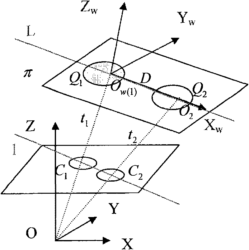
[0018] figure 1 Shown is a schematic diagram of the projection of the calibration object proposed by the present invention on the image plane. The two arbitrary circles used for calibration are on the plane π, OXYZ is the camera coordinate system, O w x w Y w Z w is the world coordinate system, where O w Now on the center of the left circle in the figure (it can also be on the center of the right circle in the figure), Z w The axis is parallel to the normal direction of the plane π. Assuming that the internal parameter matrix of the camera is K, then according to the pinhole model, where (u 0 , v 0 ) represents the principal point position, f 1 / f 2 is the aspect ratio, s is the tilt factor, these are invariant parameters, which are known in the present...


PUM


Abstract

The invention relates to a method for calibrating a camera by any two coplanar circles, and two non-concyclic centre coplanar circles are used as the calibration objects. A clear image is taken by thecamera for the calibration objects, to define the equations of two elliptical shadows in the images and solve the coordinates of the image points of the focoids. The image point coordinates of the focoids and the shadow equations of absolute secondary curves are utilized to define the focal distance of the camera; a world coordinate system is set up, with the center of any of the two circles as the origin, and Z axis is parallel with the normal direction of the plane of the two circles. A rotation matrix is defined according to the relation between blanking points, blanking lines and the elliptical shadows; the solved position, of the world coordinate system, under the camera coordinate system is the right translation vector. The method of the invention can easily and conveniently defineall variable parameters every time when the camera is calibrated, can realize the wholly automatic calibration, reduce calculation errors arisen by human intervention, and is particularly suitable fornon-contact industrial inspection and the vision-based independent navigation system.

Description

technical field [0001] The invention relates to a camera calibration method using two arbitrary coplanar circles, which can accurately determine the camera focal length, rotation matrix, translation vector and other parameters. The invention belongs to the field of advanced measurement technology, and is especially suitable for camera calibration in computer stereo vision, non-contact industrial detection and vision-based autonomous navigation system. Background technique [0002] The purpose of camera calibration is to use specific calibration objects to determine the internal and external parameters of the camera. Camera calibration is the basic requirement for obtaining three-dimensional information from two-dimensional images in the field of computer vision, and it is an essential step to complete many visual tasks. With the popularity of cameras, many non-vision professionals need a simple and flexible calibration method to help them complete vision-related work. Came...

Claims


Application Information

Patent Timeline
Patent Type & Authority Patents(China)
IPC IPC(8): G06T7/00
Inventor 黄茂祥郑银强刘允才
Owner SHANGHAI JIAO TONG UNIV
Why Eureka
Try Eureka