Interconnection lock for intelligent wireless network

A wireless network and intelligent technology, applied in the field of intelligent wireless network network locks, can solve the problems of high cost of laying wires, limited control distance, high cost of laying wires, etc., and achieves convenient management, wide range, and reduced use and maintenance costs. Effect

Inactive Publication Date: 2008-12-24
胡科
View PDF0 Cites 20 Cited by
  • Summary
  • Abstract
  • Description
  • Claims
  • Application Information

AI Technical Summary

Problems solved by technology

This system of remote control and management by laying a local area network has the following shortcomings in practical applications: 1. The control distance is limited, and its control distance is at most 1500 meters. If the room to be managed is not in a building, or even exceeds The door lo

Method used


Image

  • Interconnection lock for intelligent wireless network

Examples


Embodiment 1

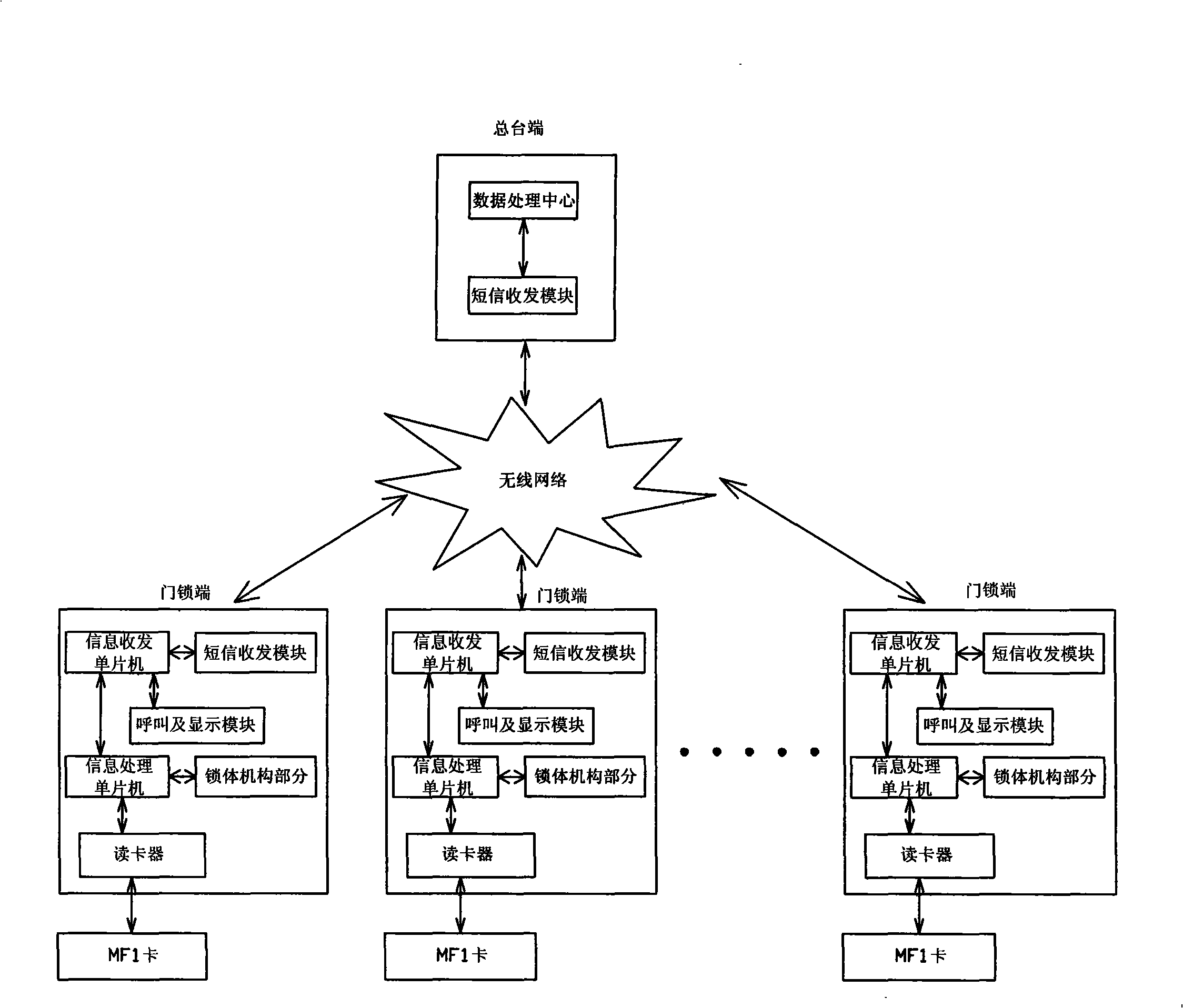
[0018] Embodiment 1: After the user gets the MF1 card key, he can go to the hotel or any room in the hotel to check in. When the user takes the key card to the sensing area of ​​the door lock and is sensed by the card reader in the door lock, this When a customer checks in, the following conditions are required: one is that the customer has not registered in other rooms, the other is that the room is empty and not occupied by other customers, and the other is that there is still money in the customer's account. Of course, whether there is money in the customer's account is a check-in condition, and the main station needs to make a corresponding judgment and then send a text message to the lock for management. If the first two check-in conditions are met, then when the customer checks in, the SMS transceiver module inside the lock will send a text message to the main station to inform the main station that the customer has registered and checked in and the room number, and the m...

Embodiment 2

[0020] Embodiment 2: When the user presses the check-out button on the inner lock of the door, the SMS module will send the check-out information to the main station through the information sending and receiving MCU inside the door lock, and the main station will receive the corresponding information. The information in the database will be called out for calculation, judgment and processing, such as stopping billing, etc. At the same time, the user's account balance and other information will be sent to the user's mobile phone, so that the user can understand his consumption situation, and then the user will go out of the room, close the door, and swipe the card Complete check out.

Embodiment 3

[0021] Embodiment 3: When the user encounters an emergency and needs help, he can press the emergency call button on the inner lock of the door, and the information sending and receiving single-chip microcomputer inside the door lock end controls the SMS module to send the distress message to the main station end, and the main station end receives the emergency call button. After receiving the prompt, send the corresponding distress information to the on-duty personnel, and then the on-duty personnel will come to help. If necessary, the "SOS" button can also be linked with the public security organ.


PUM


Abstract

The invention relates to an intelligent wireless network door interlock which is used for a door lock management system adopted in occasions such as hotels, restaurants, departments and rental rooms, etc. The intelligent wireless network door interlock comprises a front desk terminal, a door lock terminal and a non-contact IC card and is characterized in that: the intelligent wireless network door interlock is also provided with a wireless network which connects and manages the front desk terminal and a plurality of door lock terminals. The intelligent wireless network door interlock of the invention has novel design and utilizes the wireless network and a short message system to control the door lock system and carry out corresponding management, thus having large information coverage area without being limited by the location; the management is convenient, intelligent and economic, therefore, the intelligent wireless network door interlock is especially suitable for the remote monitoring.

Description

Technical field: [0001] The invention relates to an intelligent wireless network networked lock, in particular to a door lock management system suitable for remote management of hotels, hotels, apartments, rental houses and other places. Background technique: [0002] Because of the large number of rooms in apartments, rental houses, hotels, hotels and other places, it is very inconvenient and error-prone to rely on manual management of the door locks. Therefore, the existing door lock management systems in these places are generally connected by RS485 bus through the laying of local area networks. The main station terminal and the door locks of each room, and the gateway and router in the middle receive and transmit signals to realize the management of the door locks, so that remote control and management can be realized within a building or within 1500 meters. This system of remote control and management by laying a local area network has the following shortcomings in prac...

Claims


Application Information

Patent Timeline
IPC IPC(8): G07C9/00
Inventor 胡科
Owner 胡科
Why Eureka
Try Eureka