Rail vehicle driving wheel system without swing at curve bend
A technology of oscillating drive and driving wheel, which is applied in the field of rail logistics, can solve problems such as increased production costs, reduced reliability and maintainability, and technological complexity of the driving wheel system, and achieves the effect of simplifying the structure
Inactive Publication Date: 2010-11-10
NANJING UNIV OF AERONAUTICS & ASTRONAUTICS
View PDF0 Cites 0 Cited by
- Summary
- Abstract
- Description
- Claims
- Application Information
AI Technical Summary
Problems solved by technology
The complexity of the structure leads to the process complexity and production cost of the driving wheel system increase, and the reliability and maintainability decrease
In addition, due to the processing of arc-shaped rails, special pressure forming equipment and production personnel are required, which further increases production costs
Method used
View moreImage
Smart ImageViewing Examples
Examples
Embodiment Construction
Login to View More PUM
 Abstract
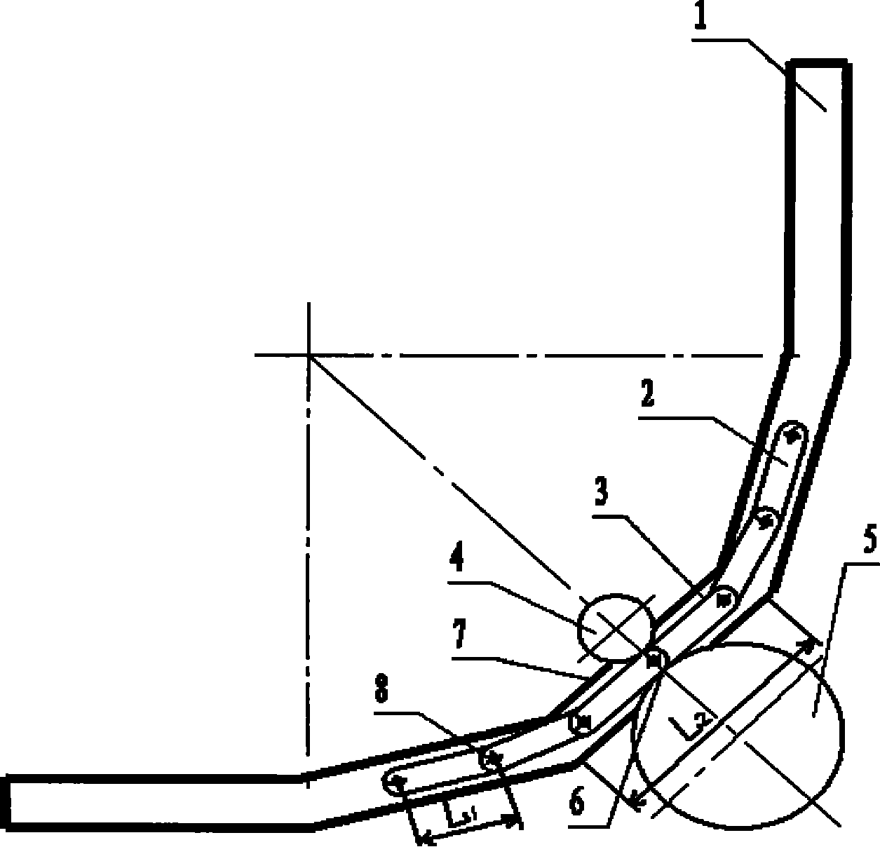
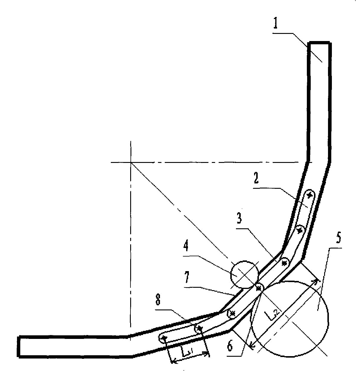
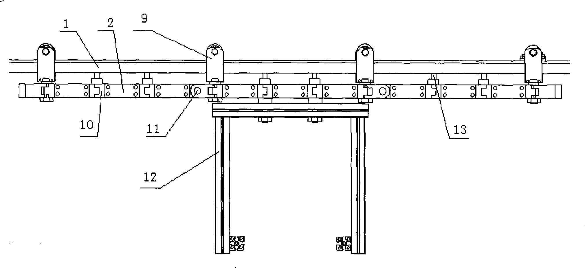
A railcar bend non-swing drive wheel system belongs to the technical field of rail logistics and consists of a rail (1), a drive rod (2) and a drive wheel system; wherein, the drive rod (2) is integrated with the body of the railcar as a part of the body of the railcar; the drive wheel system includes a motor, a drive wheel (5) connected with the motor and a riding wheel (4) matched with the drive wheel; when the drive rod (2) enters the drive wheel system, the drive wheel and the riding wheel generate a positive pressure under the effect of a pre-tightening force; a friction force for driving is instantly generated when the motor drives the drive wheel to rotate; the railcar bend non-swing drive wheel system is characterized in that the drive rod consists of n sections of drive sub-rods;besides, the neighboring drive sub-rods are connected by a rotating pair; the swerve location of the rail consists of m sections of linear fitting sections of the swerve rail. The railcar bend non-swing drive wheel system reduces the complexity of the drive wheel system, thereby improving the reliability of the drive wheel system and effectively reduces the maintenance cost.
Description
Rail car curve without swing driving wheel system Technical field The invention relates to a non-oscillating drive wheel system for a rail car on a curved road, and belongs to the technical field of rail logistics. Background technique At present, the known friction-driven track logistics system is composed of a track, a drive rod and a drive wheel system, and the drive rod is a part of the car body. The driving wheel system is composed of the driving wheel connected with the motor, the supporting wheel used in conjunction with the driving wheel, a series of spring systems and rotating pairs. When the driving rod integrated with the car body enters the driving wheel system, the driving wheel and supporting wheel will generate positive pressure under the preload of the spring system. When the motor drives the driving wheel to rotate, it will generate frictional force for driving. However, since the arc-shaped track is adopted at the turning point, and the drive rod is a lo...
Claims
Login to View More Application Information
Patent Timeline
 Patent Type & Authority Patents(China)
IPC IPC(8): B61C11/00B65G41/02
Inventor 臧铁钢楼佩煌唐敦兵叶文华
Owner NANJING UNIV OF AERONAUTICS & ASTRONAUTICS
Features
- R&D
- Intellectual Property
- Life Sciences
- Materials
- Tech Scout
- Unparalleled Data Quality
- Higher Quality Content
- 60% Fewer Hallucinations
Learn More Browse by: Latest US Patents, China's latest patents, Technical Efficacy Thesaurus, Application Domain, Technology Topic, Popular Technical Reports.
© 2025 PatSnap. All rights reserved.Legal|Privacy policy|Modern Slavery Act Transparency Statement|Sitemap|About US| Contact US: help@patsnap.com


