Super large workspace spherical face hinge

A spherical hinge and working space technology, which is applied in the direction of manufacturing tools, manipulators, and pivot connections, can solve the problems of small working space, small swing range of the output rod, and small swing range of the output rod of the spherical hinge, so as to increase the swing work space, performance improvement

Inactive Publication Date: 2008-12-31
YANSHAN UNIV
View PDF2 Cites 17 Cited by
  • Summary
  • Abstract
  • Description
  • Claims
  • Application Information

AI Technical Summary

Problems solved by technology

[0005] The existing spherical hinges all have a common shortcoming: the swing range of the output rod is small, namely:
[0008] The problem of the small swing range of the output rod of the spherical hinge has not been well solved, and the impact on engineering applications is various. For example, the working space of the parallel machine tool is affected by the spherical hinge to a certain extent. Unable to achieve larger working space requirements; Mechanism and robot mechanism are restricted by spherical hinges, and their actual working space is small; spherical (joint) hinges in humanoid robots have small working space and cannot meet the requirements of limb movement, etc.

Method used


Image

  • Super large workspace spherical face hinge
  • Super large workspace spherical face hinge
  • Super large workspace spherical face hinge

Examples


Embodiment 1

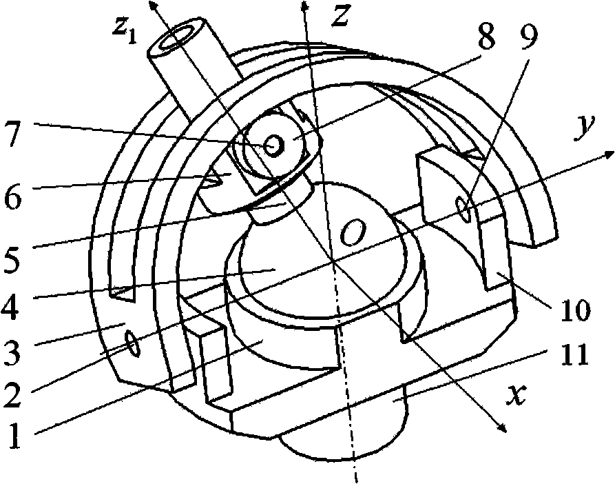
[0020] figure 1 It is the first embodiment disclosed by the present invention, and it is a new type of spherical hinge with a double-ear bracket fixed type and a large working space. It consists of a support unit, an output unit and a spherical sub-unit. The support unit includes a double-ear bracket 10, a lower support rod 11 and a U-shaped shift fork 3 and a pin shaft (2, 9) that forms a rotational connection with the double-ear bracket 10. The output unit includes an output rod 5, a rotating bracket 6, support pins (7, 7') and support rollers (8, 8'). The spherical sub-unit includes a supporting ball socket 1 , a ball head 4 and a U-shaped shift fork 3 . Wherein, the double-ear bracket 10 is fixedly connected with the lower support rod 11 as a whole, and is fixed with the support ball socket 1 at the coincident point of the ball center of the ball socket and the ball center of the hinge at the same time, and the rotation axis of the support ball socket 1 is connected with...

Embodiment 2

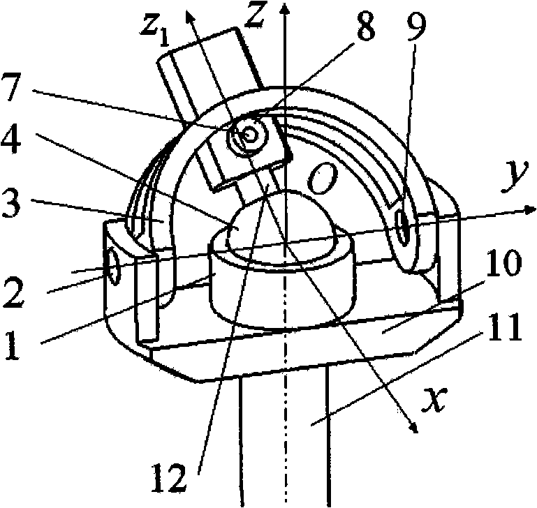
[0029] figure 2 It is the second embodiment disclosed by the present invention, and it is a new type of spherical hinge with a large working space and a rotating double-ear bracket. It consists of support unit, output unit and spherical sub-unit. The support unit includes a double-ear bracket 10, a lower support rod 11 and a pin shaft (2, 9); the output unit includes a square output rod 12, a support pin shaft (7, 7') and a support roller (8, 8' ); the spherical sub-unit includes a supporting ball socket 1, a ball head 4 and a U-shaped shift fork 3. Wherein the difference with Embodiment 1 is: the double-ear support 10 can rotate unrestricted around the axis of the lower support rod 11 (the upper part is axially positioned); the U-shaped shift fork 3 is placed inside the double-ear support 10; the pin shaft ( 7, 7') and support rollers (8, 8') are directly installed and positioned with the square output rod 12 (removing the rotating bracket), and the axis of the pin shaft (...

Embodiment 3

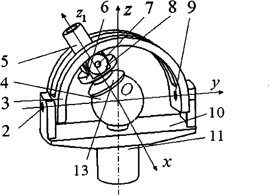
[0033] image 3It is the third embodiment disclosed by the present invention, and it is a new type of ball / socket transposition spherical hinge with a large working space. It consists of a support unit, an output unit and a spherical sub-unit, the support unit includes a double-ear bracket 10, a lower support rod 11 and a pin shaft (2, 9); the output unit includes an output rod 5, a rotating support frame 6, Support pin shafts (7, 7') and support rollers (8, 8'); Compared with Example 1, the difference is that: the position of the ball head 4 and the original supporting ball socket 1 are exchanged, and the lower supporting rod 11 is fixed at the center point of the ball, and the size of the supporting ball socket 1 is changed from the original hemispherical It is reduced to a ball gap, called the movable ball socket 13, which is fixed at the lower end of the output rod 5 (on the condition that the axis of the output rod coincides with the rotation axis of the movable ball soc...


PUM


Abstract

The invention discloses a spherical hinge which is provided with a large operating space. The spherical hinge is characterized in that a double-lug supporting frame (10) and a lower supporting rod (11) are fixedly connected with a supporting ball socket (1) into a whole, the double-lug supporting frame (10) is rotationally connected with a U-shaped shifting fork (3) through pins (2 and 9), the U-shaped shifting fork (3) is installed at the outer side of the double-lug supporting frame (10), a rotating supporting frame (6), the pins (7 and 7`) on the rotating supporting frame and supporting rollers (8 and 8`) are nested on an output rod (5) together, and the lower end of the output rod (5) is fixed with a ball head (4) centrally and is arranged in the supporting ball socket (1); the U-shaped shifting fork (3) is a semicircular arc cylindrical combined body, pin holes are arranged at both ends of the U-shaped shifting fork, and a radial sealed long groove internally and externally transparent and taking the middle plane of axial width as a symmetrical plane is arranged along the circumferential direction; the output rod (5) penetrates through the sealed long groove and can swing reciprocally in the sealed long groove. The spherical hinge has the advantages that the swinging space of the output rod is large, the structure is simple, and the volume is small, etc. The important basic unit in mechanism, namely the performance of the spherical hinge is changed in the spherical hinge, thereby bringing important influence to the mechanical design in engineering.

Description

technical field [0001] The invention relates to a spherical hinge with a large working space, and belongs to the field of mechanism robots or machinery. Background technique [0002] As a rotatable connection, the spherical hinge usually consists of a ball head connected to an output rod and a ball socket fixedly connected to a support rod. When one end is fixed, the other end has three rotational degrees of freedom. In the field of mechanics and robotics, this rotatable connection is called a spherical pair. Theoretically, these two elements must be in stable and reliable contact. However, in engineering, this kind of spherical pair cannot be separated no matter it is under pressure or tension, so it must be guaranteed in structural design. [0003] At present, there are two types of typical structures of the main and commonly used spherical hinges: the transversely split ball-and-socket type. That is, the transverse section perpendicular to the axis of the support rod ...

Claims


Application Information

Patent Timeline
Patent Type & Authority Applications(China)
IPC IPC(8): F16C11/06B25J11/00
Inventor 周玉林高峰
Owner YANSHAN UNIV
Why Eureka
Try Eureka