Receiving and adjusting circuit for high-frequency electromagnetic wave test signal

A technology for conditioning circuits and testing signals, applied in electromagnetic wave detection, electrical/magnetic detection for logging records, electromagnetic field characteristics, etc. and other problems, to achieve stable performance, high signal-to-noise ratio and measurement accuracy, and simple function implementation.

Inactive Publication Date: 2008-12-31
CHINA NAT OFFSHORE OIL CORP +1
View PDF0 Cites 3 Cited by
  • Summary
  • Abstract
  • Description
  • Claims
  • Application Information

AI Technical Summary

Problems solved by technology

[0002] The high-frequency electromagnetic wave test signal receiving and conditioning circuit is mainly composed of an attenuation module, a gating module, an amplification module, a frequency mixing module and a filtering module, among which: the filtering module is used to select the intermediate frequency signal from the high frequency and intermediate frequency signals output by the mixing module , at present, the filter module generally uses an active band-pass filter, and the phase-frequency characteristic of the active band-pass filter is relatively sensitive, and is easily affected by the signal amplitude, thus affecting the testing accuracy of the high-frequency electromagnetic wave logging tool
At the same time, if figure 1 As shown, the current mixing module is built with the chip SST441, and the structure is relatively complex. At the same time, due to the precision errors of the resistors, inductors and other components, the gain linearity and phase linearity will also be affected to a certain extent.
In addition, there are problems such as mutual interference between the probes of high-frequency electromagnetic wave logging tools, weak received signals, and the possibility that the input signal may exceed the signal amplitude range when it is directly amplified.

Method used


Image

  • Receiving and adjusting circuit for high-frequency electromagnetic wave test signal
  • Receiving and adjusting circuit for high-frequency electromagnetic wave test signal
  • Receiving and adjusting circuit for high-frequency electromagnetic wave test signal

Examples


Embodiment Construction

[0022] A high-frequency electromagnetic wave test signal receiving and conditioning circuit proposed by the present invention can be applied to an array-type high-frequency electromagnetic wave logging instrument with multiple receiving probes and multiple frequencies. Compared with the prior art, the circuit has better functions. Simple, more stable performance, and higher signal-to-noise ratio, the following uses a dual-frequency receiving structure instrument with 8 receiving probes as an example to illustrate the present invention in detail:

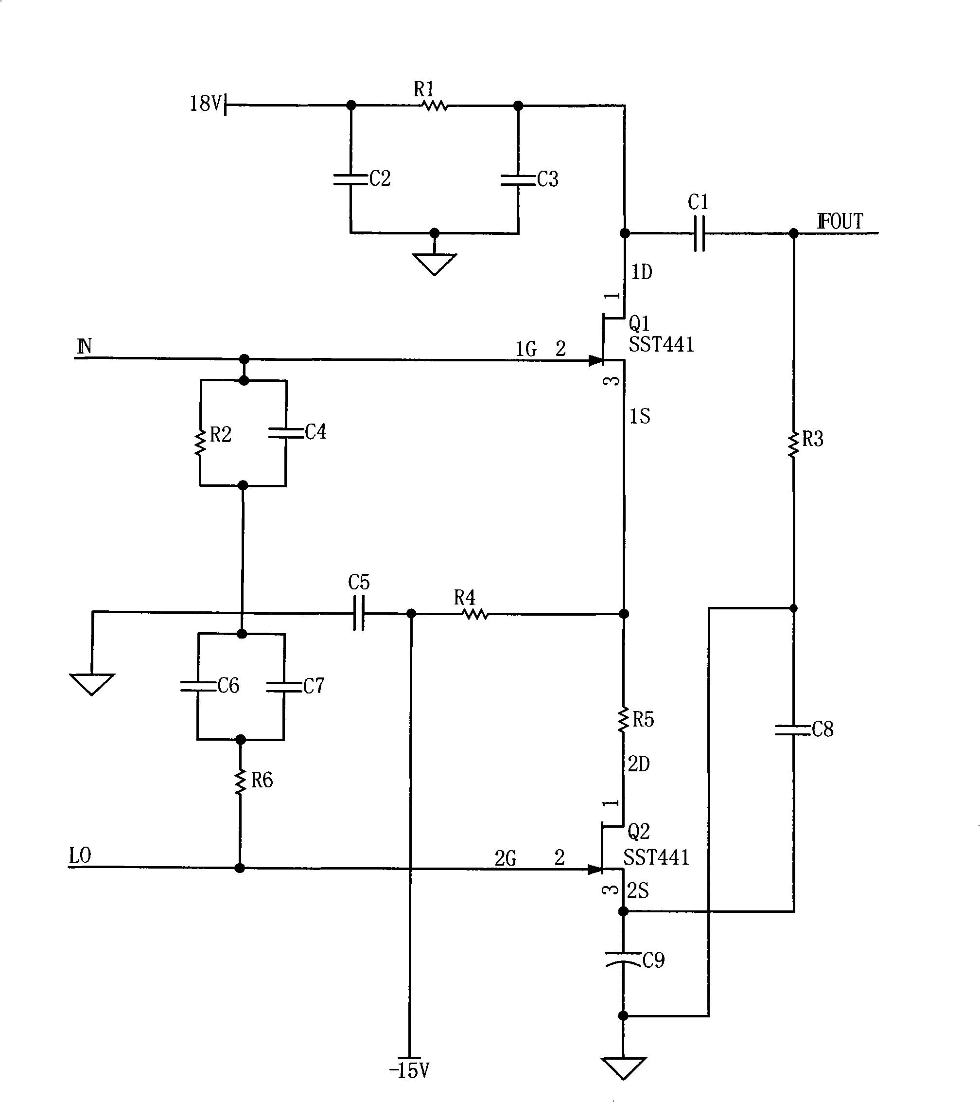
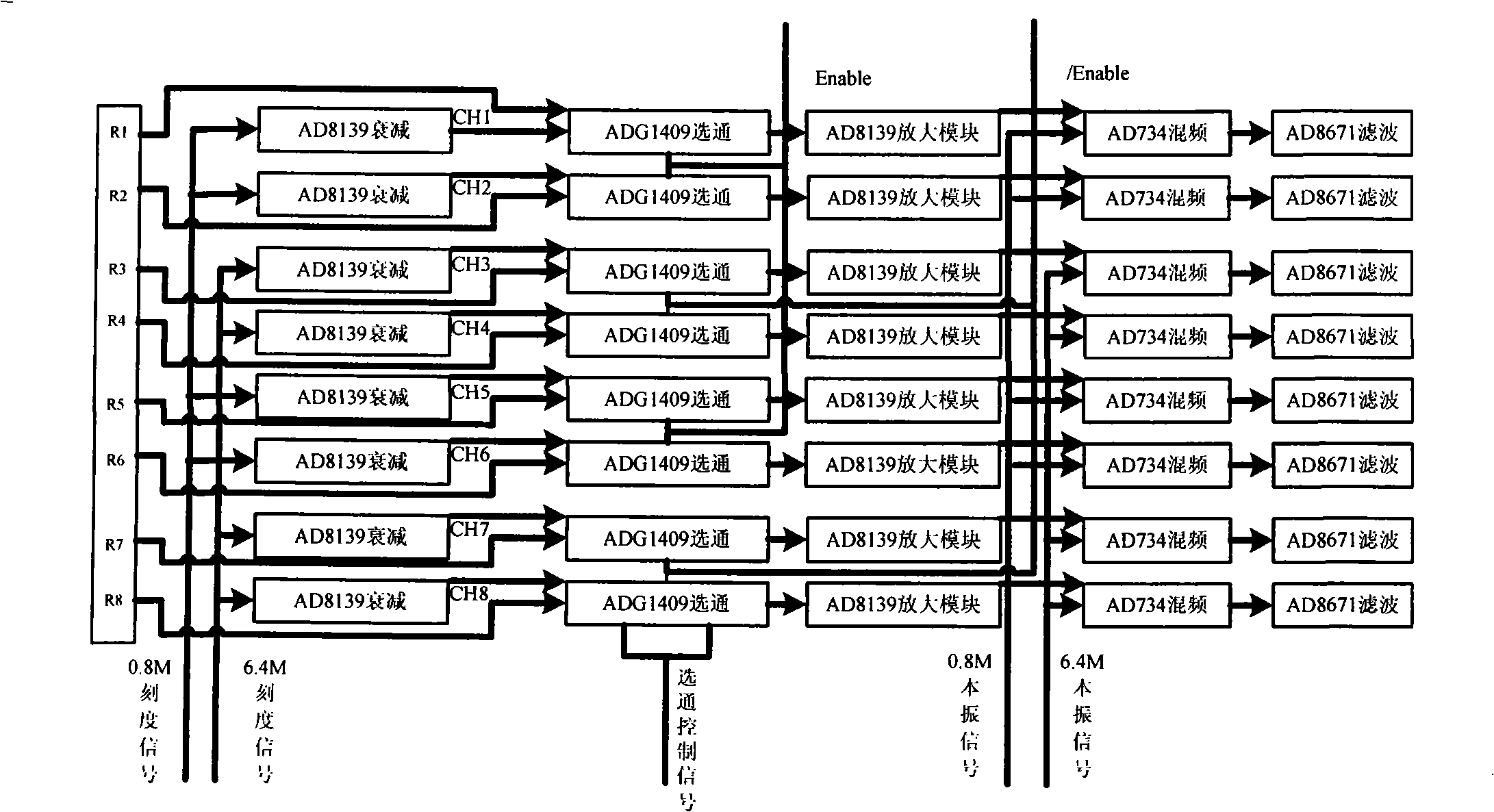
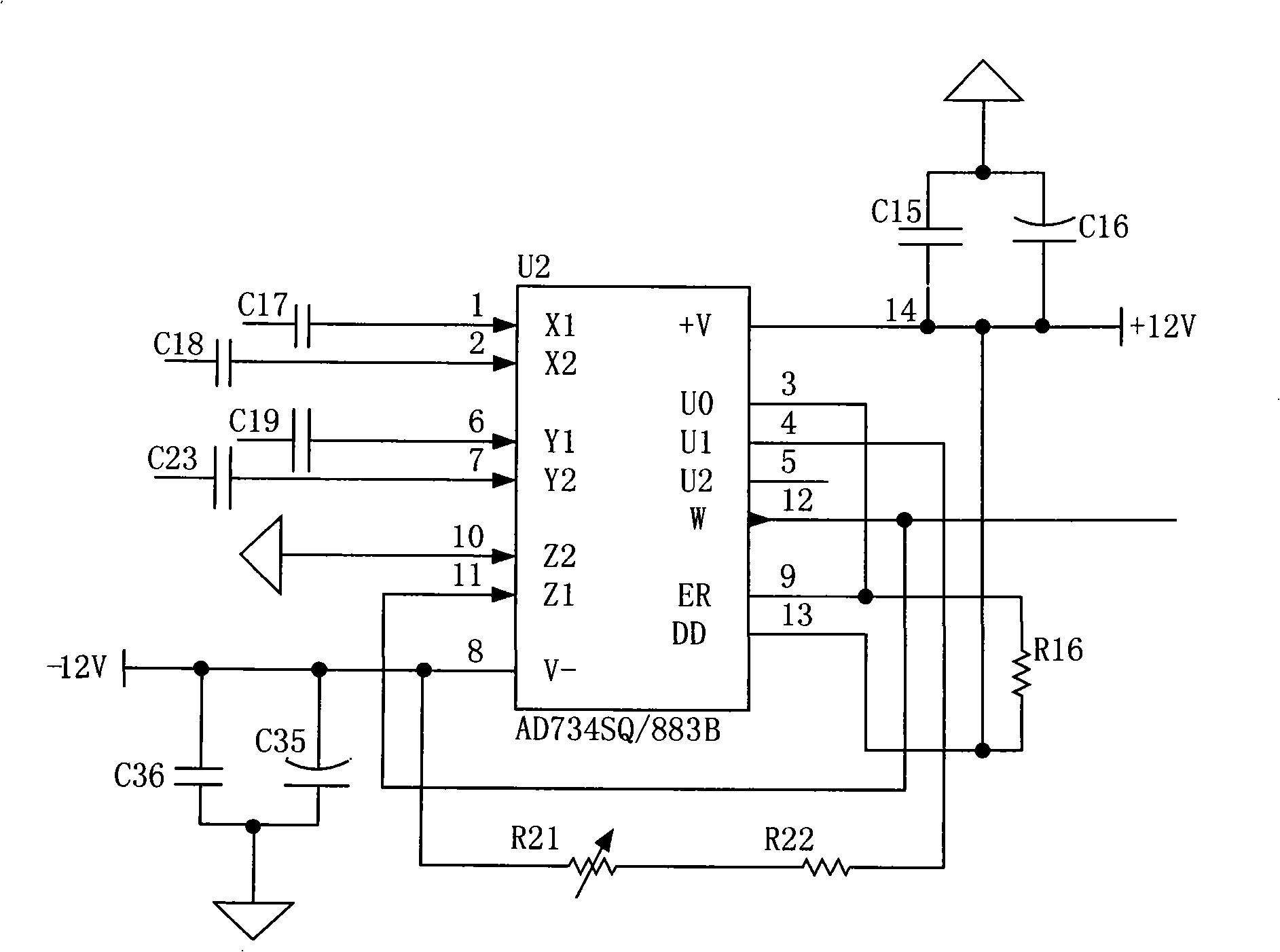
[0023] The receiving and conditioning circuit, the overall structure is as follows figure 2 As shown, it is mainly composed of attenuation, gating, amplification, mixing and filtering modules. Compared with the existing technology, there are four main innovations, as follows:

[0024] 1. The mixer adopts an integrated multiplier circuit, which can ensure the gain linearity and phase linearity in a large dynamic range, meet the measu...


PUM


Abstract

The invention relates to a high-frequency electromagnetic wave test signal receiving and conditioning circuit, comprising an attenuation module, a gate module, an amplifying module, a frequency mixing module and a filter module which adopts an active low-pass filter which are sequentially and electrically connected, and the high-frequency electromagnetic wave test signal receiving and conditioning circuit further adopts an integrated multiplier, two levels of differential amplification and two levels of differential attenuation. Compared with the prior art, the signal receiving and conditioning circuit can be applicable to a high-frequency electromagnetic wave test instrument, thereby realizing the simpleness, the more stable performance, the higher signal-to-noise ratio and the higher measurement precision.

Description

technical field [0001] The invention relates to high-frequency electromagnetic wave testing, in particular to a high-frequency electromagnetic wave testing signal receiving and conditioning circuit. Background technique [0002] The high-frequency electromagnetic wave test signal receiving and conditioning circuit is mainly composed of an attenuation module, a gating module, an amplification module, a frequency mixing module and a filtering module, among which: the filtering module is used to select the intermediate frequency signal from the high frequency and intermediate frequency signals output by the mixing module , at present, the filter module generally uses an active band-pass filter, and the phase-frequency characteristic of the active band-pass filter is relatively sensitive, and is easily affected by the signal amplitude, thus affecting the testing accuracy of the high-frequency electromagnetic wave logging tool. At the same time, if figure 1 As shown, the current...

Claims


Application Information

Patent Timeline
Patent Type & Authority Applications(China)
IPC IPC(8): G01R29/00G01R29/08G01V3/30
Inventor 马明学张雷师奕兵李焱骏
Owner CHINA NAT OFFSHORE OIL CORP
Why Eureka
Try Eureka