Mill deltoid device

A technology of flat square and lathe bed, applied in the field of flat square milling device, can solve the problems of difficulty in adjusting and straightening precision, influence of milling processing precision, high labor intensity of operators, etc., to reduce labor intensity, simple overall structure, and ensure The effect of precision

Inactive Publication Date: 2009-01-07
JIANGSU GANGBAO ROLLER
View PDF0 Cites 19 Cited by
  • Summary
  • Abstract
  • Description
  • Claims
  • Application Information

AI Technical Summary

Problems solved by technology

The existing technology usually uses a desktop milling machine to act as a milling flat head or a flat square or a keyway milling. However, the disadvantage of using a desktop milling machine is: after each plane is milled, the roll needs to be reinstalled. Re-adjustment, so the labor intensity of the operator is high, especially because the adjustment accuracy is difficult to control, it is easy to affect the milling accuracy, and then affect the use effect of the roll in the future
Although the use of double-sided milling machines can reduce the frequency of reinstallation and adjustment, for example, there is no intermediate link of installation and adjustment for milling and flattening heads, and it can be done in one go, but there is still a reinstallation and adjustment for processing square heads. Therefore, it is still not enough to fully reduce the labor intensity of operators and to fully guarantee the processing quality; in addition, the price of double-sided milling machines is extremely expensive, which is not affordable for ordinary small and medium-sized enterprises

Method used


Image

  • Mill deltoid device
  • Mill deltoid device
  • Mill deltoid device

Examples


Embodiment 1

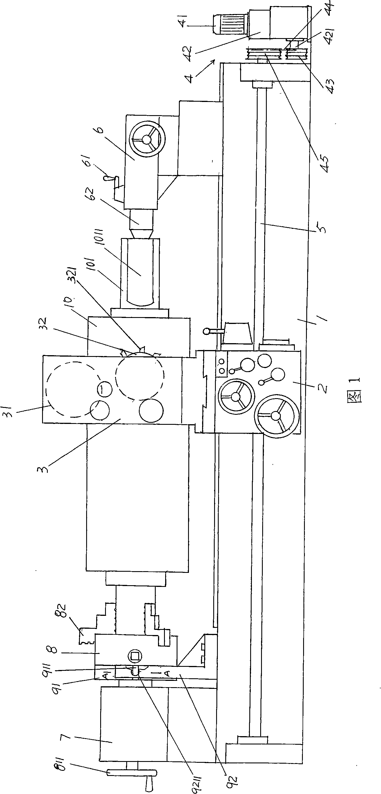
[0019] Please see Fig. 1, provided lathe bed 1, this lathe bed 1 adopts the bed of lathe in the prior art, and the mode of adopting has three, and the one, directly buy from lathe manufacturer, the 2nd, from discarded Take its bed on the lathe, the 3rd, buy the bed of the lathe from the second-hand equipment swap market, and the tool box 2 configured on the lathe bed 1 is the same example. The milling tool box 3 is installed on the tool box 2. For the milling tool box 3, it is recommended to use the milling tool box on the milling machine produced and sold by the milling machine manufacturer, for example, the model 3ZP I produced by China Shanghai Yongxin Milling Machine Co., Ltd. - Milling cutter box for type 2 milling machines. This milling cutter box 3 is equipped with motor 31 (ie motor) and plane milling cutter disc 32. In view of the above description, it can be seen that the lathe bed 1, milling, and tool boxes 2, 3 are all prior art, so the applicant no longer makes s...

Embodiment 2

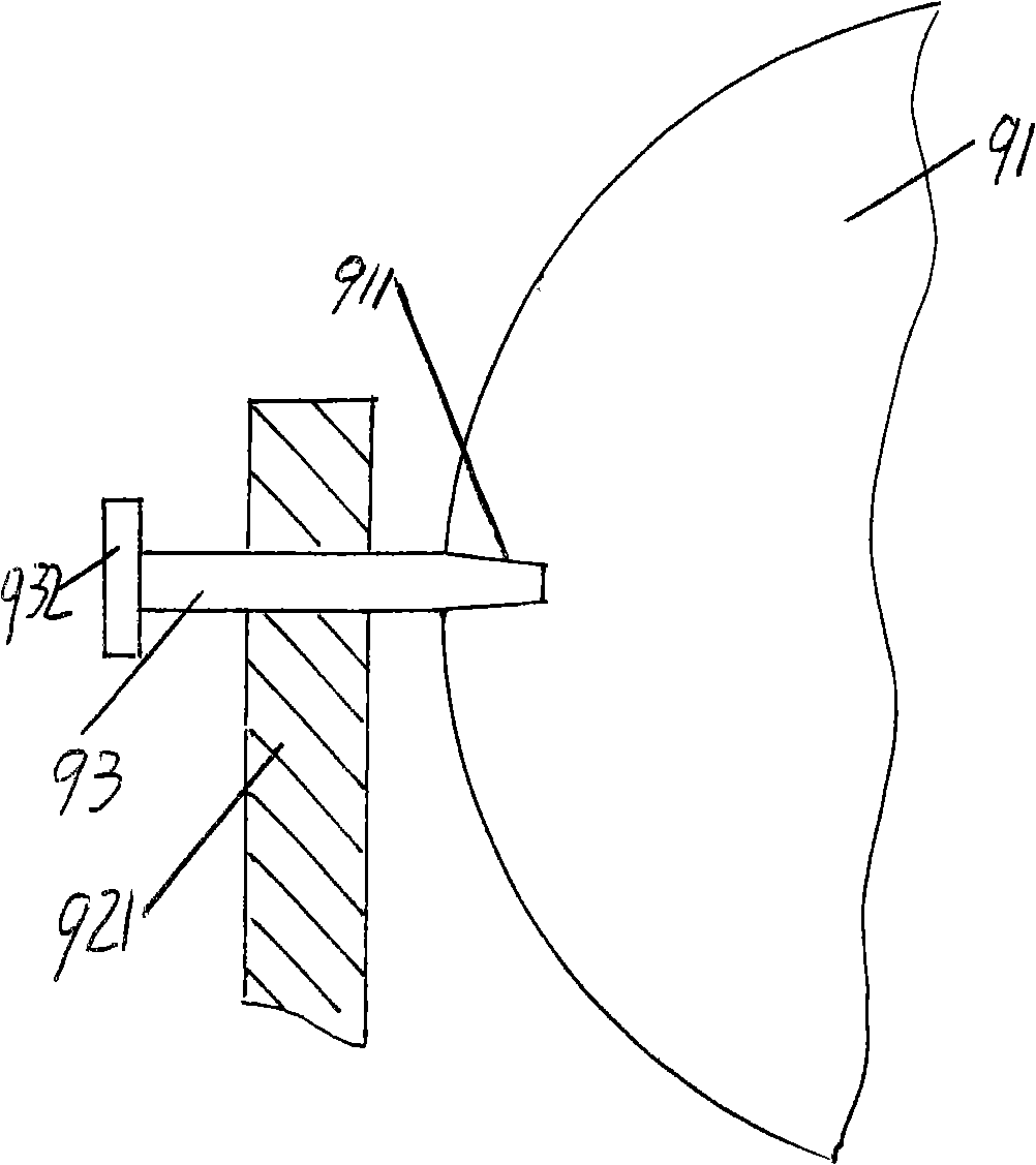
[0025] please see Figure 4 In addition to the four first indexing grooves 911 as described in Embodiment 1, a second indexing groove 913 and a third indexing groove 914 are provided on the edge of the indexing plate 91 . Form an angle of 15° between the second indexing groove 913 and one of the first indexing grooves 911 in the four first indexing grooves 911; and the third indexing groove 914 and the four first indexing grooves 911 One of the first indexing grooves 911 forms an included angle of 45°. More specifically, the four first indexing grooves 911 described in Embodiment 1 are provided at four equal divisions of the circumference of the indexing plate 91, that is, four equal divisions of the circumference of the indexing plate 91 are respectively opened. A first indexing groove 911, therefore, the second indexing groove 913 in the present embodiment is to be opened at the two fourteen equal parts of the circle of the indexing plate 91, the same example, the third ind...


PUM


Abstract

A flat and square head milling device belongs to the technical field of milling machinery, and comprises a lathe body, a power transmission mechanism, a feed box shaft, a tail seat, a chuck, a main shaft seat of the chuck, and a dividing control mechanism, wherein the lathe body is provided with a feed box; a milling cutter box is mounted on the feed box; the power transmission mechanism corresponds to one end of the lathe body; the two ends of the feed box shaft are pivoted at the two ends of the lathe body in the length direction thereof, and are in transmission connection with the power transmission mechanism; the middle part of the feed box shaft is matched with the feed box; the tail seat is mounted on the lathe body; the main shaft seat of the chuck is mounted at the other end of the lathe body, and corresponds to the tail seat; the chuck is mounted at one end of the main shaft of the chuck; the middle part of the main shaft of the chuck is pivoted on the main shaft seat of the chuck; the other end of the main shaft of the chuck is extended onto the main shaft seat of the chuck and equipped with a hand wheel; and the dividing control mechanism comprises a dividing disk, a dividing disk locating frame and a locating key. The device has the advantages that the labor intensity of operators can be reduced, flat or square heads can be precisely milled at the ends of a roller or similar workpieces, and the whole structure is simple.

Description

technical field [0001] The invention belongs to the technical field of milling machines, and in particular relates to a square milling and flattening device, which is used for machining and installing planes or key grooves on necks of roller-type workpieces. Background technique [0002] The above-mentioned concept of milling and flattening refers to the milling of the necks of the two ends of the rolls used in the steel rolling industry for workpieces with large lengths and diameters, which are symmetrical to each other, that is, two square planes separated by 180° for installation. (flat head) or square planes distributed at 90° (square head). The existing technology usually uses a desktop milling machine to act as a milling flat head or a flat square or a keyway mill. However, the disadvantages of using a desktop milling machine are: after each plane is milled, the roll needs to be reinstalled. After the reinstallation, it is necessary to Re-adjustment, so the labor inte...

Claims


Application Information

Patent Timeline
Patent Type & Authority Applications(China)
IPC IPC(8): B23C7/02B23Q5/00B23Q16/02B23Q16/04
Inventor 吴泛舟龚文炳
Owner JIANGSU GANGBAO ROLLER
Why Eureka
Try Eureka