Check patentability & draft patents in minutes with Patsnap Eureka AI!

Shaking valve rotary cylinder type variable displacement device and its rotary engine

A technology of rotating engine and cylinder, applied in the field of power machinery, can solve the problems of complex engine structure, low working efficiency, poor sealing performance, etc., and achieve the effects of light weight, improved efficiency and good sealing performance

Active Publication Date: 2009-01-07
门振宇
View PDF4 Cites 1 Cited by
  • Summary
  • Abstract
  • Description
  • Claims
  • Application Information

AI Technical Summary

Problems solved by technology

[0004] The first object of the present invention is to propose a simple structure, small volume and high working efficiency for the defects and deficiencies of the existing variable displacement fluid machinery, such as complex structure, large volume, low working efficiency and poor sealing performance. Valve rotary cylinder type variable capacity mechanism
[0005] The second purpose of the present invention is to propose a simple structure, small volume, small vibration, low energy consumption and deficiencies in view of the defects and deficiencies of the existing engine for more than one hundred years, such as complex structure, high energy consumption, poor sealing performance and large vibration. Low, good sealing performance rocking valve rotary cylinder rotary engine

Method used


Image

  • Shaking valve rotary cylinder type variable displacement device and its rotary engine
  • Shaking valve rotary cylinder type variable displacement device and its rotary engine
  • Shaking valve rotary cylinder type variable displacement device and its rotary engine

Examples


Embodiment Construction

[0028] The present invention will be described in further detail below in conjunction with accompanying drawing description and specific embodiment:

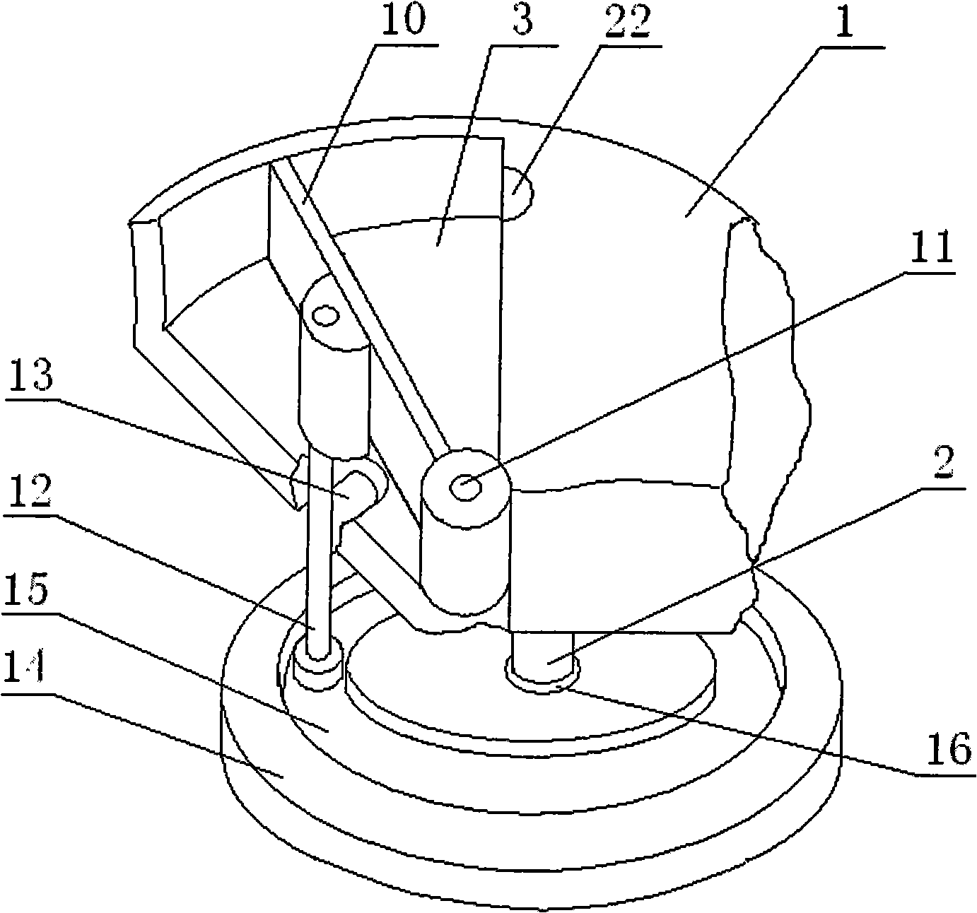
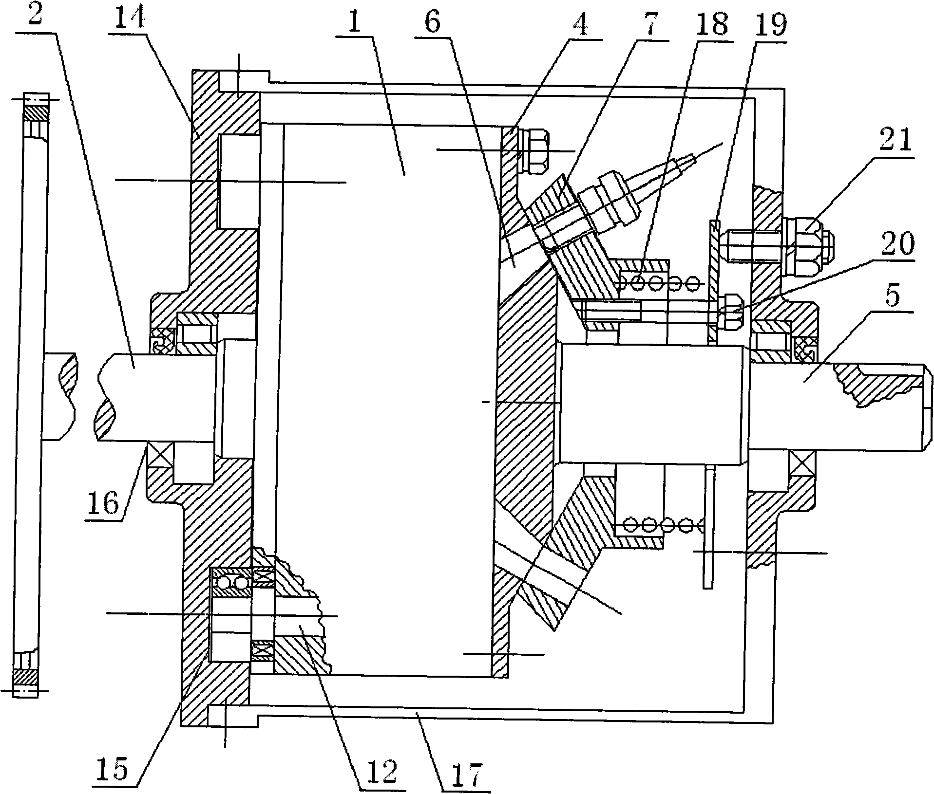
[0029] see figure 1 , image 3 , Figure 4 , a rocking valve rotating cylinder type variable capacity mechanism of the present invention, comprising a cylinder body 1 and a rocking valve 10, the cylinder body 1 is disc-shaped, and a main shaft 2 is arranged on the axis of one side of the cylinder body 1, A fan-shaped chamber 3 is opened on the end surface of the other side of the cylinder body 1, and a flow distribution seat 4 is fixed close to the fan-shaped chamber 3, and a rotating shaft 5 passes through the flow distribution seat 4 and is fixed on the axis of the cylinder body 1, or the corresponding cylinder body 1. The axis is fixed on the outer wall of the flow distribution seat 4. The flow distribution seat 4 has a through hole 6 corresponding to the fan-shaped chamber 3. A flow distribution cover 7 is inserted into th...


PUM


Abstract

The present invention relates to a rocking valve and rotating cylinder type transfiguration mechanism and a rotating engine thereof belonging to the dynamic machinery field. A cylinder body (1) is a disk shape. An axle center at one side of the cylinder body (1) is provided with a principal axis (2), an end face at the other side of the cylinder body (1) is provided with a fan-shaped cavity chamber (3), and a flow distribution base (4) is fixed closely to the fan-shaped cavity chamber (3). A flow distribution cover (7) is mounted into a rotating shaft (5) and is closely and annularly contacted with a through hole (6) position at the external wall of the flow distribution base (4). A rocking plug (10) is correspondingly arranged in the fan-shaped cavity chamber (3). One end of the rocking plug (10) is fixed near the circle center of the arc line of the fan-shaped cavity chamber (3) by a pin roll (11). The rocking plug (10) is also provided with a rocking shaft (12) which is plugged into an oblong slide way (15) on a slideway cover (14). The rocking valve and rotating cylinder type transfiguration mechanism has compact structure, few parts and components, small size, light weight, good tightness, small vibration, high working efficiency and convenient maintenance, can be made into a gasoline engine and a diesel engine and also can be made into fluid dynamic machinery such as a pump, a hydraulic motor, an air compressor, etc.

Description

technical field [0001] The invention relates to an engine or a hydraulic motor, in particular to a valve-rotating-cylinder type variable displacement mechanism and a rotary engine thereof. It belongs to the field of power machinery. Background technique [0002] The core parts and technical points of hydraulic motors, hydraulic pumps, compressors, and even internal combustion engines working under high temperature, high speed, and high pressure conditions are the variable capacity, sealing and energy saving of the mechanism. [0003] When an ordinary internal combustion engine is working, the piston makes a high-speed linear reciprocating motion in the cylinder to complete the four cycles of "inhalation, compression, combustion, and exhaust". power. Cylinder, piston and crank-connecting rod mechanism bring complex mechanism, bulky, low efficiency, high energy consumption, large vibration and other insurmountable problems. The movement characteristics of the "triangular ro...

Claims


Application Information

Patent Timeline
IPC IPC(8): F01C1/00F01C20/10F02B53/02F02B53/06F02B55/10
CPCY02T10/17F01C20/10F02B57/10F02B53/06Y02T10/12
Inventor 王修斌杨道远梁番焕周双彧黄虎
Owner 门振宇
Features
  • R&D
  • Intellectual Property
  • Life Sciences
  • Materials
  • Tech Scout
  • Unparalleled Data Quality
  • Higher Quality Content
  • 60% Fewer Hallucinations
Learn More