Multipath hydraulic change-over valve

A technology of hydraulic reversing valve and one-way valve

Inactive Publication Date: 2009-01-07
浙江海克力液压有限公司
View PDF1 Cites 13 Cited by
  • Summary
  • Abstract
  • Description
  • Claims
  • Application Information

AI Technical Summary

Problems solved by technology

The invention patent with the Chinese patent number 200510023936.7 discloses an integral manual multi-way directional valve for loaders, which shows the basic structure of the existing integral manual multi-way directional valve, which can solve the problem of the original integral manual multi-way directional valve to a certain extent. The multi-way reversing valve inherently has the problems of large internal leakage and large reversing control force, but there are still the following defects:
[0004] 2. There are only two steel balls on the two ends of a straight line on the steel ball seat. Four arc ring grooves need to be made on the bush to correspond to the four gears (boom up, neutral, down, floating). After that, it is easy to deviate from the coaxial direction in another direction;
[0005] 3. There are longitudinal throttling grooves and annular balance grooves on the valve stem of the bucket and the valve stem of the boom. The two are isolated from each other, and it is easy to generate radial unbalanced force;
[0007] The overall effect of the above factors will make the hydraulic valve easy to generate various mechanical forces during the reversing process, and these mechanical forces will further make the valve stem deviate from the center position of the valve stem hole on the valve body, resulting in greater hydraulic clamping force. The operating force of the hydraulic valve is heavy during the working process, and the phenomenon of "valve stuck" is easy to occur; the friction of the corresponding parts of the hydraulic valve increases, and the service life of the hydraulic valve is shortened

Method used


Image

  • Multipath hydraulic change-over valve
  • Multipath hydraulic change-over valve
  • Multipath hydraulic change-over valve

Examples


Embodiment Construction

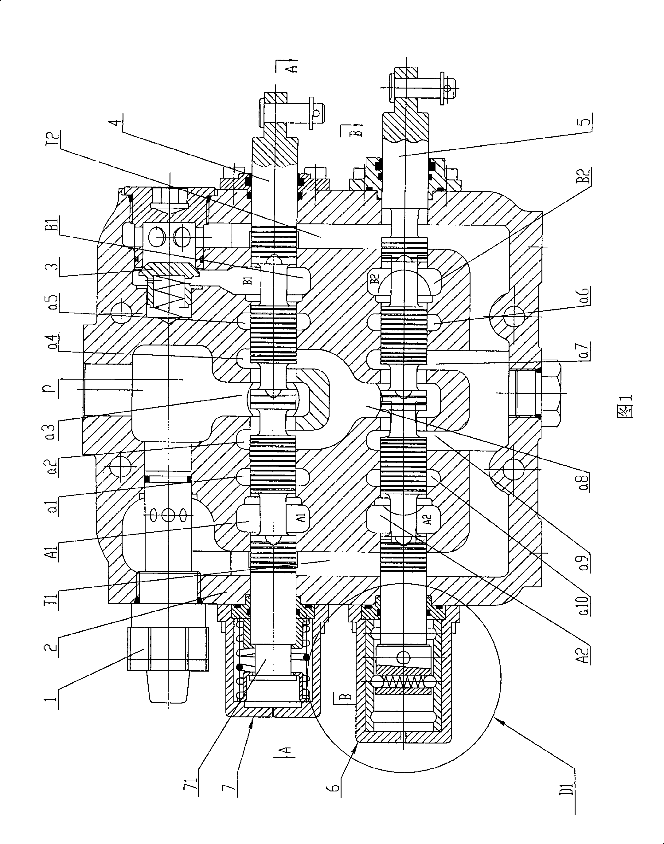
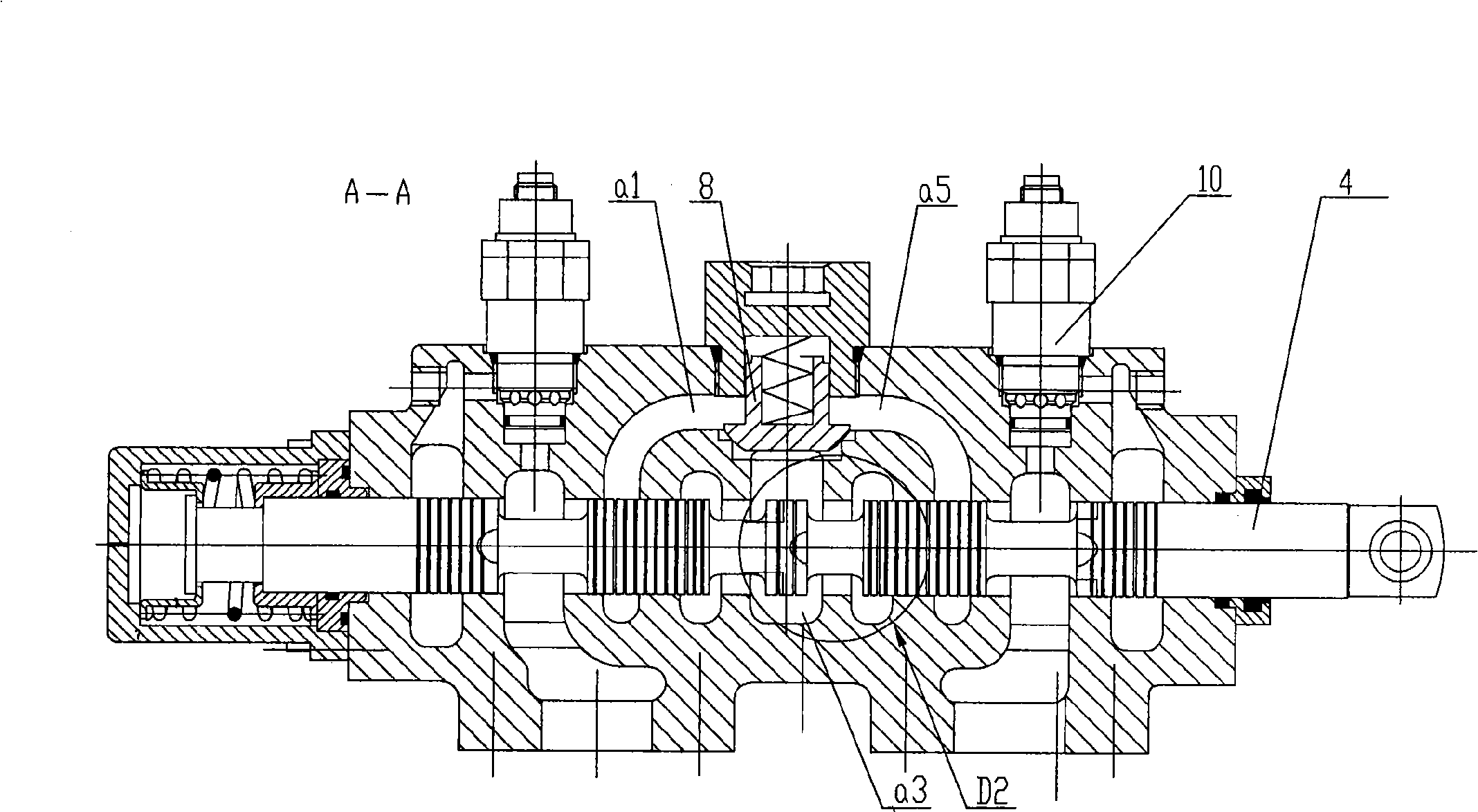
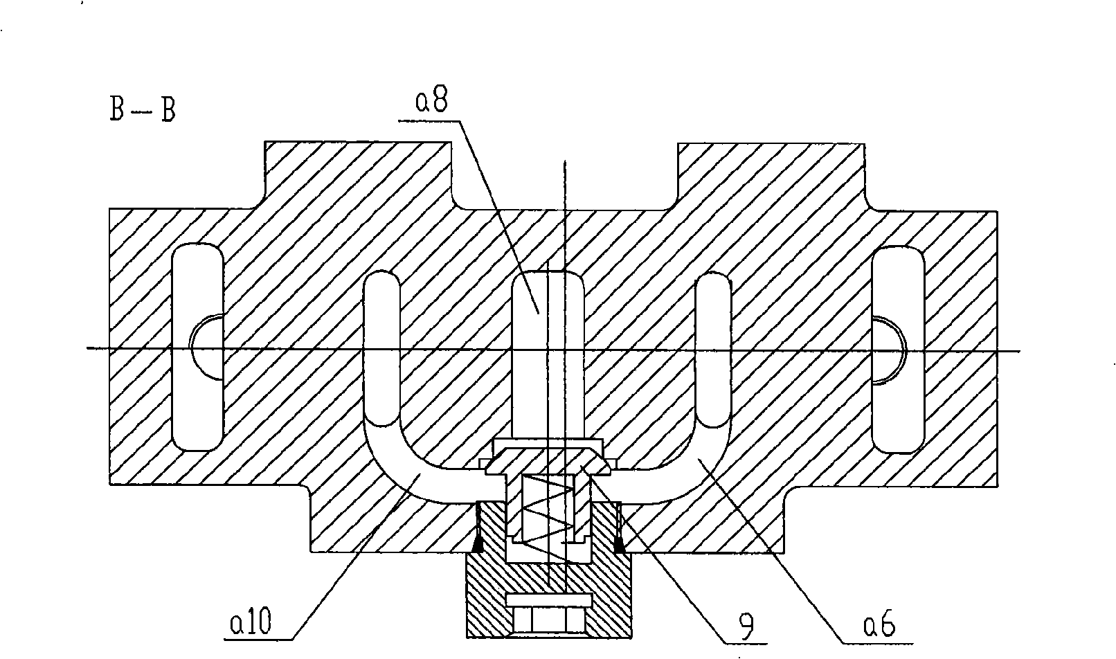
[0025] Referring to Figure 1- image 3 , multi-way hydraulic reversing valve, including valve body 2, bucket valve stem 4, boom valve stem 5, main safety valve 1, overload valve 10, bucket load holding check valve 8, boom load holding check valve 9. Oil supply valve 3, rotary bucket valve stem positioning device 7, boom valve stem positioning device 6, etc., valve body 2 is provided with 9 oil passages respectively on the rotary bucket joint valve stem hole and the boom joint valve stem hole, The oil passages on the stem hole of the bucket union are, from left to right, the left return oil passage T1, the left working port oil passage A1, the left working port oil inlet passage a1, the left unloading oil passage a2 of the bucket union, The oil inlet passage a3 of the bucket union, the right unloading oil passage a4 of the bucket union, the oil inlet passage a5 of the right working port, the oil passage B1 of the right working port, the right return oil passage T2, and the oil ...


PUM


Abstract

The present invention relates to a multi-path hydraulic reversing valve, which comprises a valve body, a turning bucket valve rod, a movable arm valve rod, a main safety valve, an overload valve, a turning bucket load-retaining one-way valve, a movable arm load-retaining one-way valve, an oil-supplementing valve, a turning bucket valve rod-positioning unit and a movable arm valve rod-positioning unit. The tail ends of the valve rods in the positioning units are provided with stepped holes, wherein, the deep holes are connected with the front ends of positioning blocks by threads, and the shallow holes serve as positioning holes to be tightly fitted with the middle cylindrical surfaces of the positioning blocks. The bodies of the turning bucket valve rod and the movable arm valve rod are provided with longitudinal throttling grooves and multiple annular compensating grooves, and the throttling groove is intersected with at least one annular compensating groove. Valve rod holes on the valve body, through which the valve rods pass, are stepped, wherein, the deep holes are fitted with the valve rods, and the shallow holes serve as positioning holes to be tightly fitted with the cylindrical surface of the flange part of a pressing plate. The inner wall of a lining is provided with three arc-shaped steel ball-positioning ring grooves. The present invention can reduce the operating force of the hydraulic valve, resolve the jamming problem of the hydraulic valve, reduce the abrasion of the related parts of the hydraulic valve and prolong the service life of the hydraulic valve, and the multi-path hydraulic reversing valve is characterized by simple structure and reliable operation.

Description

technical field [0001] The invention relates to hydraulic machinery, in particular to the improvement of a multi-way reversing valve suitable for the working hydraulic system of the loader. Background technique [0002] At present, the working hydraulic system of the domestic wheel loader is equipped with a multi-way reversing valve, which has a simple structure and is easy to maintain. The invention patent with the Chinese patent number 200510023936.7 discloses an integral manual multi-way directional valve for loaders, which shows the basic structure of the existing integral manual multi-way directional valve, which can solve the problem of the original integral manual multi-way directional valve to a certain extent. The multi-way reversing valve inherently has the problems of large internal leakage and large reversing control force, but there are still the following defects: [0003] 1. The steel ball seat in the positioning device is threadedly connected to the end of t...

Claims


Application Information

Patent Timeline
Patent Type & Authority Applications(China)
IPC IPC(8): F16K11/10F16K31/12F15B13/02
Inventor 应世建
Owner 浙江海克力液压有限公司
Why Eureka
Try Eureka