Illuminating device and its lens used therein

A light-emitting device and lens technology, which is applied to components of lighting devices, semiconductor devices of light-emitting elements, lighting devices, etc., can solve the problems of low light extraction efficiency, achieve high light output efficiency, improve lamp efficiency, and small beam angle.

Inactive Publication Date: 2009-01-07
SHANGHAI FEILO ACOUSTICS
View PDF3 Cites 15 Cited by
  • Summary
  • Abstract
  • Description
  • Claims
  • Application Information

AI Technical Summary

Problems solved by technology

Obviously, due to the specific curved surface shape of the funnel part 58 and the up-and-down arrangement of the serrations of...

Method used


Image

  • Illuminating device and its lens used therein
  • Illuminating device and its lens used therein
  • Illuminating device and its lens used therein

Examples


Embodiment Construction

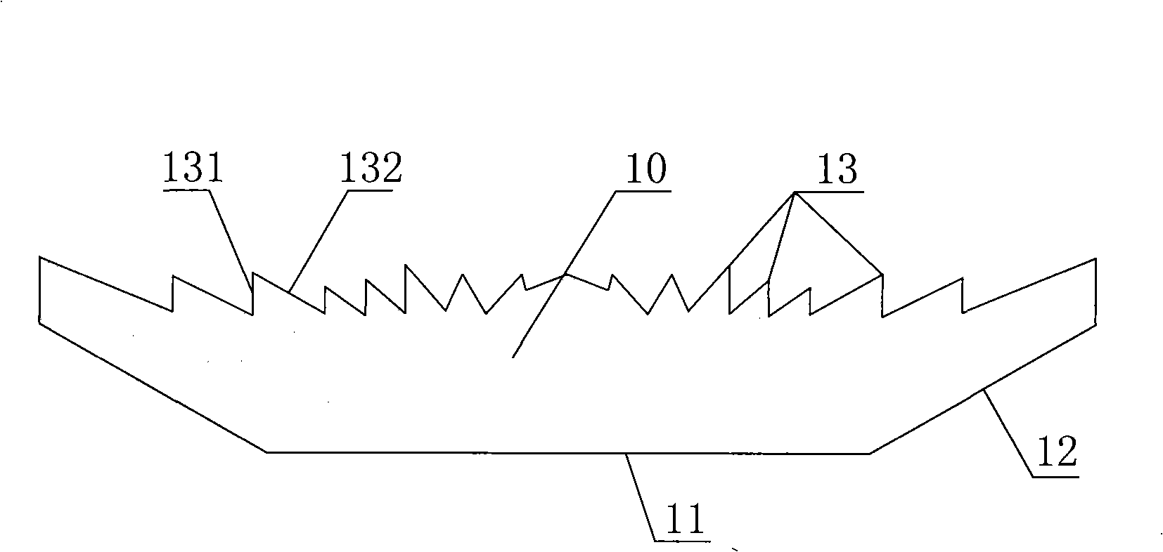
[0038] first as figure 2 , as shown in FIG. 3 , a lens 10 for a light-emitting device of the present invention is in the shape of a sheet, and its bottom surface is an incident surface 11 . The top surface of the lens is provided with multiple circles of annular serrations 13, and these serrations 13 are arranged inwardly and outwardly along the center of the lens. Figure 6 , Figure 7 and Figure 8 shown more clearly.

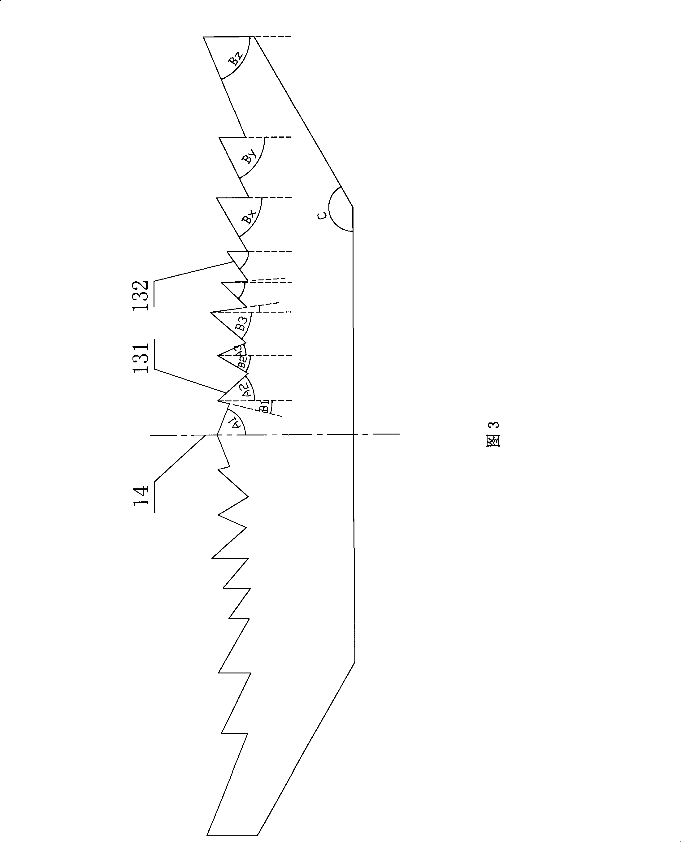
[0039] Continue to refer to figure 2 , FIG. 3 , the inner surface 132 and the outer surface 131 of the sawtooth constitute the refraction exit surface of the lens. In a section passing through the center of the lens, the cross-sectional outlines of these serrations 13 are straight lines. A preferred method is that the angles of these serrations are different, and according to the order of arrangement from inside to outside (from the center to the edge), the angles between the outer surface 131 of each serration and the central axis 14 of the lens are s...


PUM


Abstract

The invention discloses a luminescent device and a lens thereof. The lens comprises a incident surface and a refraction exit surface; the lens is in a slice shape; the subface of the lens is an incident surface; multi-circle ring-shape saw teeth are arranged on the top surface of the lens; these saw teeth are arranged along the direction from the center of the lens toward the inner and outer brims, and the inner lateral-faces and outer lateral-faces of the saw teeth form a refraction exit surface. A total reflection plane can also be arranged on the lateral face of the lens. The luminescent device comprises a light-source and the lens arranged in front of the light source. The invention can reduce the thickness of the lens to the largest extent, as a result, the light loss inside the lens is reduced, and the light emitting efficiency is improved. The very small thickness can realize a relatively small light-beam angle. Besides meeting the requirements of optically designed light-distribution curve, the utility model also has the advantages of very small thickness, high emitting efficiency and little stray loss; and the utility model can facilitate the design of lighting products.

Description

technical field [0001] The invention relates to a light-emitting device and a lens used therefor. The light-emitting device includes a light-emitting semiconductor element and a lens. The lens is used to guide the light beam emitted by the light-emitting semiconductor element to emit in a certain direction. Background technique [0002] As a new generation of environmentally friendly, efficient and long-life light sources, semiconductor light sources have gradually entered the lighting field. For example, Chinese invention patent application CN101105272A discloses an LED street lamp and its lens. The lens includes an incident surface and an outgoing surface. A pit is provided in the middle of the first side of the lens for the LED to be installed therein. The pit wall of the pit constitutes the The incident surface; the middle part of the second side of the lens is convex in an arc shape to form a pillow-shaped exit surface; and the first side of the lens is provided with a ...

Claims


Application Information

Patent Timeline
IPC IPC(8): F21V5/04F21Y101/02F21Y115/10
Inventor 庄灿阳
Owner SHANGHAI FEILO ACOUSTICS
Why Eureka
Try Eureka