Electronic detonator control chip and its connection reliability checking method

A technology for controlling chips and electronic detonators, applied in the field of pyrotechnics, can solve problems such as the inability to detect the reliability of the external connection of the chip, the inability to detect components, and affect the anti-static and anti-radio frequency safety characteristics of the detonator, so as to achieve online repeated testing and avoid Energy consumption, the effect of improving the reliability of use

Active Publication Date: 2009-01-07
南通炜天电子科技有限公司
View PDF5 Cites 35 Cited by
  • Summary
  • Abstract
  • Description
  • Claims
  • Application Information

AI Technical Summary

Problems solved by technology

However, since the above-mentioned electronic detonator control chip has no internal BIT (Bulit_In Test, self-inspection) function, the reliability of the chip itself and its external connections cannot be detected. Therefore, in the detonator production process, once the chip is installed in the detonator shell, Components connected to the chip cannot be detected
In the patent ZL200420034635.5, which uses an electronic timing circuit and external separated electronic components to realize the function of an electronic detonator, an electronic switch is used to isolate the ignition device from the detonator leg, and there is also no detection function for the connection reliability of the ignition device.
[0004] In addition, in the segmented delay detonator given in ZL98210324.7, the bridge wire is led out to the detonator foot wire through the cur

Method used


Image

  • Electronic detonator control chip and its connection reliability checking method
  • Electronic detonator control chip and its connection reliability checking method
  • Electronic detonator control chip and its connection reliability checking method

Examples


Embodiment Construction

[0068] The technical solution of the present invention will be described in further detail below in conjunction with the accompanying drawings and specific embodiments.

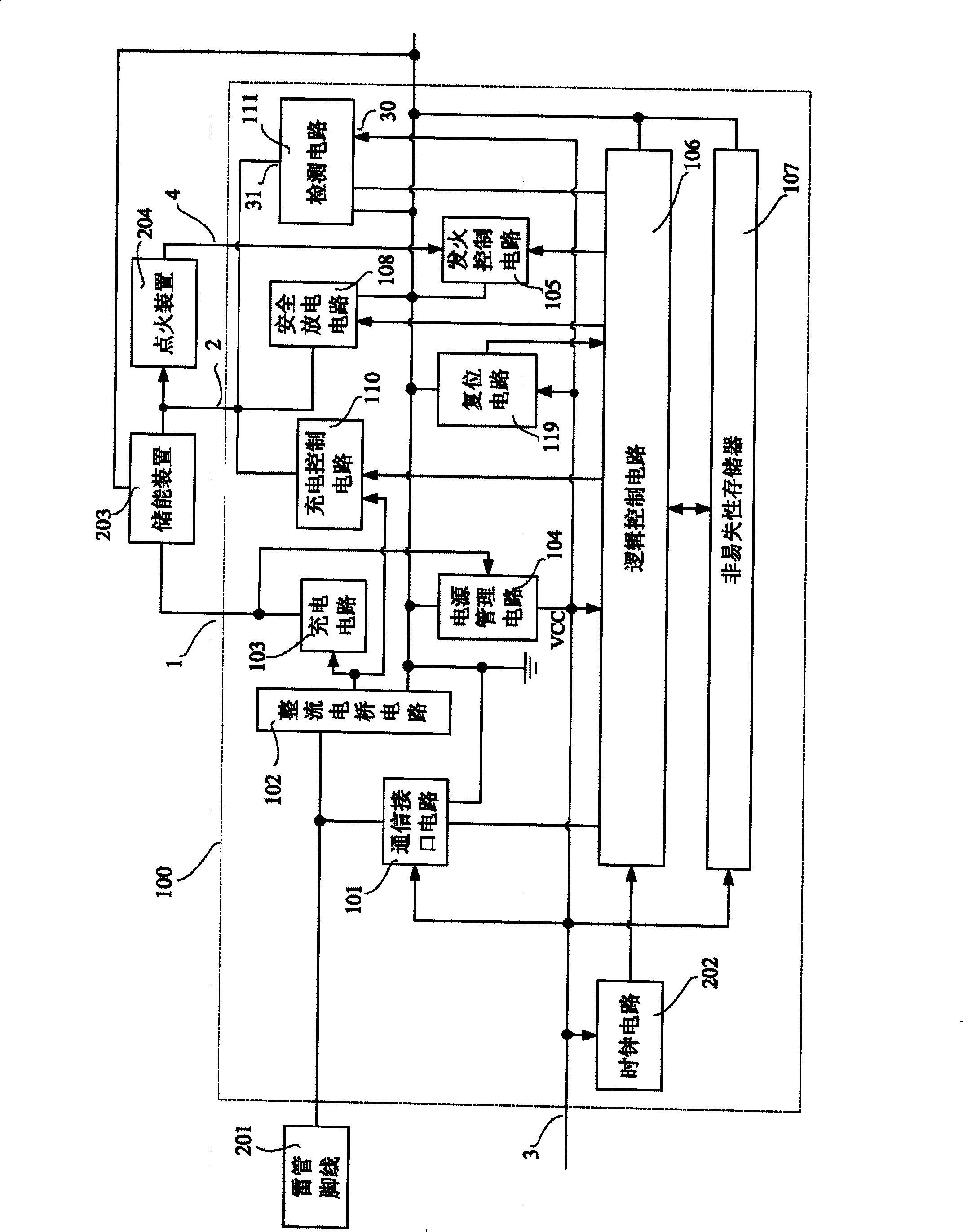
[0069] Such as figure 1 , an electronic detonator control chip 100, comprising a communication interface circuit 101, a rectifier bridge circuit 102, a charging circuit 103, a charging control circuit 110, a power management circuit 104, an ignition control circuit 105, a logic control circuit 106, and a nonvolatile memory 107 , a reset circuit 119 , a safety discharge circuit 108 , and a clock circuit 202 . One end of the charging circuit 103 is connected to the rectifier bridge circuit 102 , the other end is connected to the power management circuit 104 , and the other end is connected to the outside of the chip 100 to form a pin 1 . One end of the charge control circuit 110 is connected to the rectifier bridge circuit 102 , the other end is connected to the logic control circuit 106 , and the other end is...


PUM


Abstract

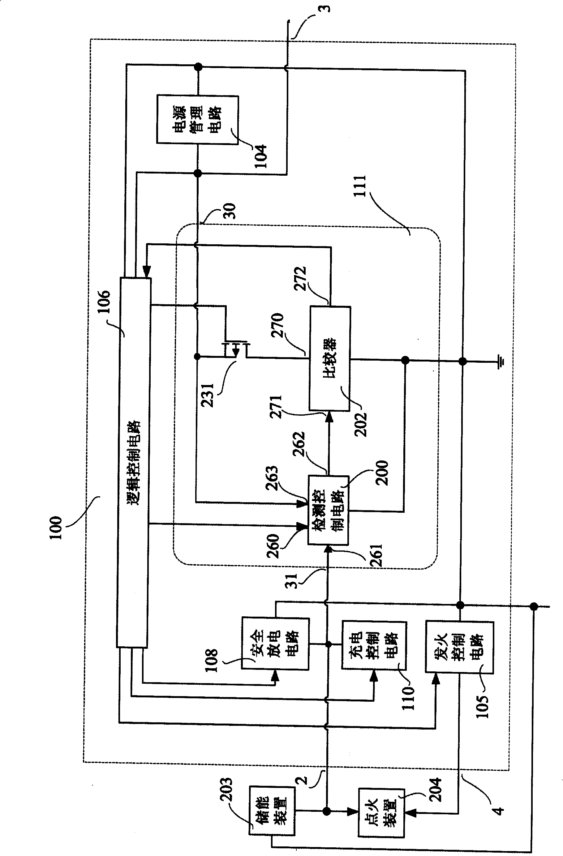
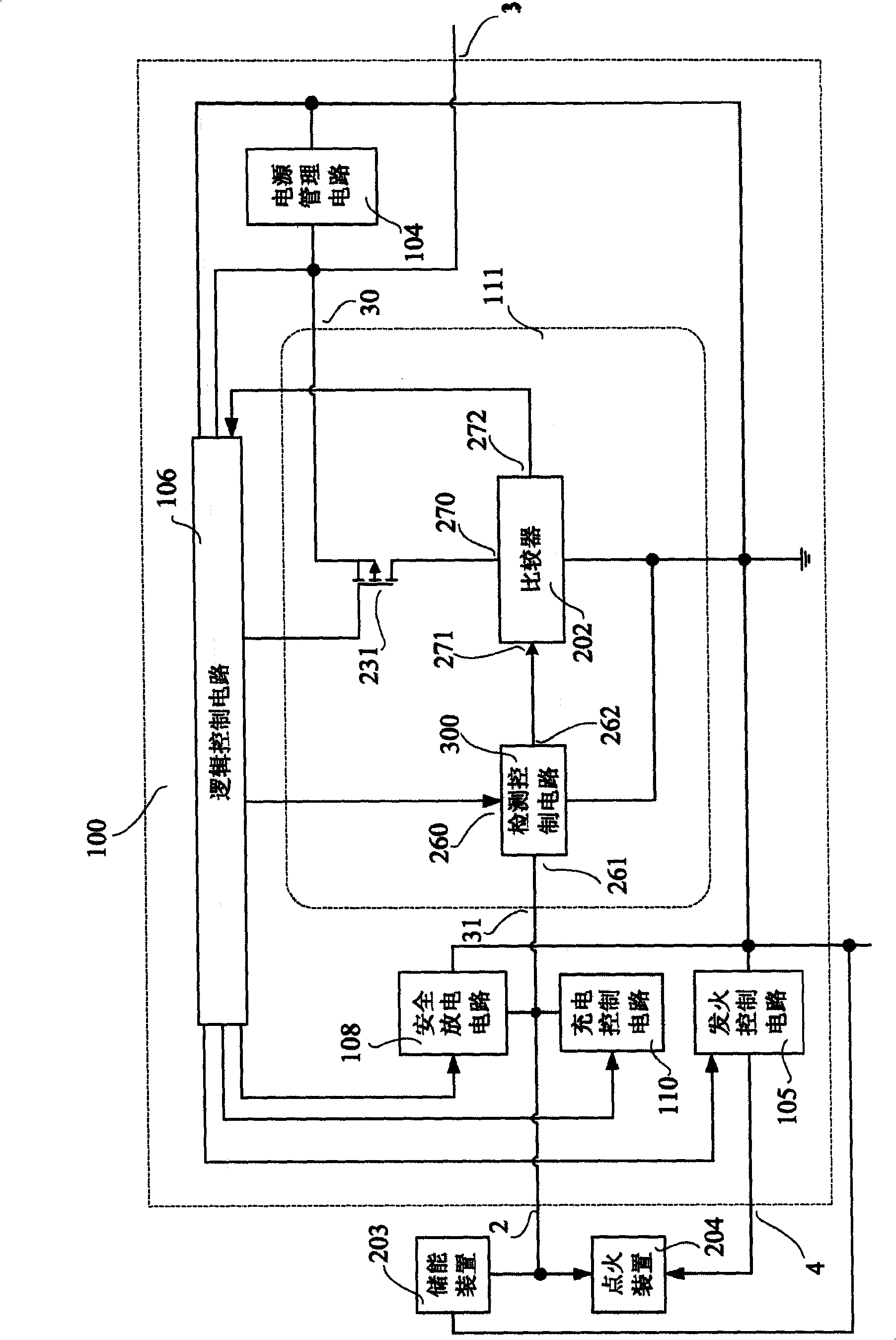
The invention provides an electronic primer control chip which comprises a charge control circuit, a power supply management circuit, an ignition control circuit, a logic control circuit, a safe discharge circuit and so on. The electronic primer control chip in particular comprises a sensing circuit. The mains input end of the sensing circuit is connected with the power supply management circuit,and the other end is connected with the logic control circuit. The signal input end is connected with the charge control circuit and the safe discharge circuit. The sensing circuit comprises a sensing control circuit, a comparator and a PMOS tube, which can adopt a Schmidt inverter. The invention further provides a method for sensing the connection reliability of the chip. Firstly, the initial state of the chip is sensed; secondly, the charge circuit is sensed; thirdly, the ignition circuit or the safe discharge circuit is sensed; fourthly, an energy storage device is charged; subsequently, the circuits which have not be sensed in the ignition circuit and the safe discharge circuit are sensed; finally, the chip is set back to the initial state. In this way, an electric primer is sensed online; and the use reliability is improved.

Description

technical field [0001] The invention relates to the field of pyrotechnics, in particular to an electronic detonator control chip with a self-detection function and a self-detection method thereof. Background technique [0002] In the 1980s, Japan, Australia, Europe and other developed countries began to study electronic detonator technology. With the rapid development of electronic technology, microelectronic technology and information technology, electronic detonator technology has made great progress. In the late 1990s, electronic detonators began to be put into application testing and marketing. [0003] As the core component of the electronic detonator, the performance of the electronic detonator control chip directly affects the performance of the electronic detonator. The electronic detonator control chip disclosed in the patent application documents ZL03156912.9 and 200820111269.7 realizes the two-wire non-polar connection of the electronic detonator, the two-way co...

Claims


Application Information

Patent Timeline
IPC IPC(8): F42C19/12
CPCF42B3/121
Inventor 颜景龙刘星李风国赖华平张宪玉
Owner 南通炜天电子科技有限公司
Why Eureka
Try Eureka